NE-M Installation Guide H5692448
850050111 Issue 03 August 2017 34
Step Action
Notes:
1. Steps show four 12V batteries per shelf – one string of -48V batteries.
2. 1 Battery Disconnect Switch per shelf shown.
Other options
• 2 Battery Disconnect Switches per shelf (left and right) (two 24V battery strings per shelf)
• 1 or 2 Anderson Disconnects per shelf
• No Battery Disconnect Switches or Anderson Disconnects - Battery cables shipped loose.
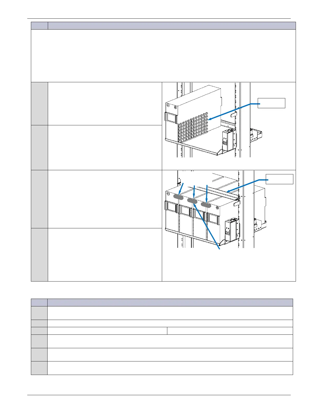
1
Place four batteries on each battery tray.
Figure 41 Place Batteries
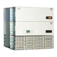
2
Position three Battery Spacers between the
batteries.
3
48V Battery Strings:
Interconnect three inter-cell bus bars to
configure one 48V battery string per the
battery manufacturer’s instructions.
24V Battery Strings:
Interconnect two inter-cell bus bars to
configure two 24V battery strings per the
battery manufacturer’s instructions.
Figure 42 Battery Inter-Cell Bus Bars
4
Attach the battery securing top rail.
External Batteries
Step Action
1
Place batteries on battery trays, battery stands, or other satisfactory supporting surface and interconnect per
manufacturer’s instructions to create 24V or 48V strings as required.
Is an external disconnect switch being used?
Yes – go to Step2. No – Finished.
2
Physically mount switch to an appropriate place and ensure it is in the OFF position prior to making any
connections
3
Connect the battery hot conductor(s) to the line side of the disconnect switch and torque connection per
manufacturer's specification.
4
Connect the load side conductor to the disconnect switch and torque connection per manufacturer's
specification.
Inter-cell
48V systems only