NE-M Installation Guide H5692448
850050111 Issue 03 August 2017 21
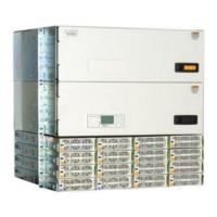
Connect Interframe Bus Bars
Step Action
Figure 19 Interframe Bus Bars
WARNING: Energy
Bus bars of systems with powered rectifiers or batteries connected provide hazardous
electrical energy.
Are Initial Frame rectifiers ON or batteries connected?
Yes – go to Step 1. No – go to Step 2.
1
Verify AC power is OFF and Batteries are disconnected.
Use appropriate lock-out tag-out procedures before continuing.
• Turn all AC breakers off and lock-out tag-out.
• Disconnect all batteries.
2
Attach 850046677 Link Buses to Primary voltage-buses and Return buses in both cabinets (4 places).
Secure with 3/8” hardware provided – Torque to 240 in-lb (27 Nm) – 9/16” socket.
3
Attach T-Bus bars & as shown (4 places).
Secure with 5/16” hardware provided – Torque to 160 in-lb (18 Nm) – 1/2” socket.
4
Attach Interframe Bus bars as shown (2 places).
Secure with M8 hardware provided – Torque to 160 in-lb (18 Nm) – 1/2” socket.
5
Cover Interframe Bus bars with two 848414611 Lexan Covers .
Remove paper covering on covers before installing.
Rear View
Rear View
5/16” Hardware
3/8” Hardware
3/8” Hardware
848414611 Lexan Cover (2)
8500051755
847760204 T-Bus Return (2)
847760196 T-Bus -48V (2)
850046677 Link Bus (4)
Interframe Buses - Front View
 Loading...