NE-M Installation Guide H5692448
850050111 Issue 03 August 2017 46
Bolt-In Breakers or TPL-C Fuse Holders
1
For bolt-in breakers only (skip this step for fuse holders)
Assemble load bus bar to breaker using provided screws, nuts, and washers.
Torque nuts to 240 in-lb – 9/16” socket.
2
Install shunt monitor cable and alarm daisy chain cable and to breaker or fuse holder.
Alarm cables daisy-chain from 850038647 cable through all bolt in breakers.
1. Connect alarm cable to pins 8 & 9.
2. Connect shunt monitor cable to pins 12 & 13 (if equipped with shunt monitor RPM).
3
Install Bolt-in breaker(s) into specified position using provided hardware.
1. Install standoffs - torque to 65 in-lb.
2. Secure load bus to standoffs with flat head screws - torque to 65 in-lb.
3. Secure breaker to load bus with 3/8” bolt, lock washer, and flat washer – torque to 240 in-
4
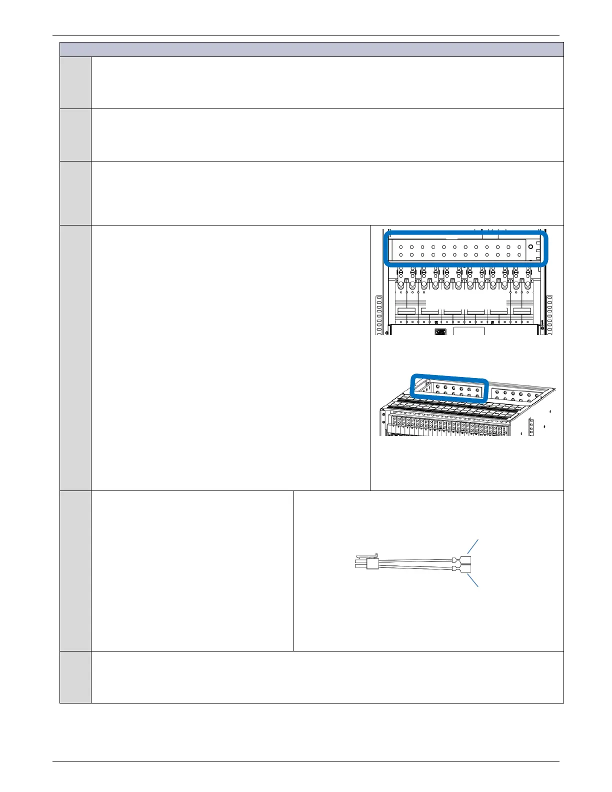
Secure Load Cable connections with provided hardware (per
cable):
(2) 3/8-16 nut or bolt
(2) 3/8-inch lock washer
(2) 3/8-inch flat washer
Torque to 240 in-lb - 9/16” socket.
Note: Load Return bar for bolt-in panel may be at the top of the
bolt-in panel or at the top of the frame.
Figure 65 Bolt-in Position Return Bar
5
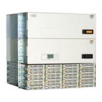
Connect breaker or fuse holder alarm to the
system.
Cabinets come equipped with an 850038647
alarm cable for each bolt-in protector panel.
Pull the 2-pin connector from the wiring
bundle along the left side of the cabinet.
Connect the leftmost (first) breaker or fuse
holder to the 2-pin connector of the
850038647 cable.
Daisy chain alarms between additional
breakers and fuse holders.
Connects to leftmost breaker of fuse holder of each panel.
Figure 66 850038647 Alarm Cable
6
Connect breaker or fuse holder shunt wires to a shunt monitor RPM (if equipped) – Figure 64
1. Route black and white shunt monitoring wires to a shunt monitor RPM on the front door.
2. Identify the shunt wire pair for labeling RPM channels.
3.
Connect shunt monitor cable to a shunt monitor RPM.
to Breaker
or Fuse
Y
W
From Battery
Bus
Alarm Fastons