NE-M Installation Guide H5692448
850050111 Issue 03 August 2017 79
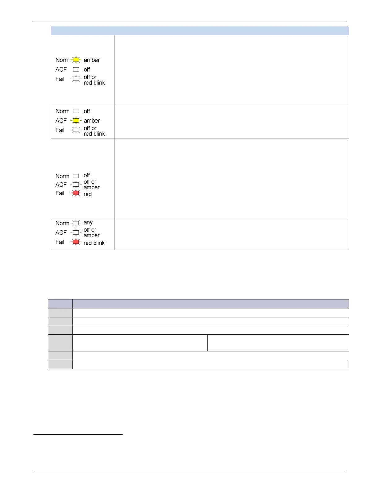
Table 11 Rectifier/Converter LEDs
Output Limit: The unit is okay and delivering maximum output:
• At max rated output
• At configured current limit
• At thermal limit
1. If rectifiers/converters are equipped with optional air filters and reporting thermal
limiting, check air filters. Clean or replace all filters if necessary.
2. View unit currents
:
Status > Rectifiers > Rectifier Currents or Status > Converters > Converter
Currents
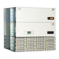
ACF - ac Fail: Rectifier input is missing or out of range.
Correct AC fault.
INF
34
- Input Fail: Converter input is out of range.
Correct converter input fault.
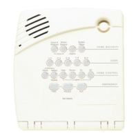
Shutdown
: The unit cannot deliver output.
• High Voltage Shutdown
• Thermal Shutdown
• Under Voltage Protect
• Component failure
1. Check rectifier or converter status on controller display to determine cause of
shutdown
2. Correct system output short, high temp, etc.
3. Remove and reinsert unit. If fault remains and other units are functioning correctly,
replace unit.
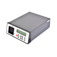
Communication Fail: Blinks to indicate the unit is not communicating with a system
controller.
Remove and reinsert unit. If fault remains and other units are communicating correctly,
replace unit.
Voltage Temp (VT)-Probes
Checking for Defective VT-Probes
(If a Voltage Channel Failure and/or Thermal Probe Failure alarm occurs)
Disconnect the first probe from its RJ-45 terminal block.
2 Run the command: Menu > Control / Operations > Uninstall Equipment.
Is the system controller green Normal LED lit?
3
Finished.
No – Reinstall the removed probe. go to Step 4.
4
Remove the next probe.
Go to Step 2. Repeat steps for all probes.
34
INF LED on converters replaces ACF on rectifiers.
35
When a rectifier or converter senses an over- or under-voltage condition, it will shutdown, wait 4 seconds, and then
attempt to restart. If the over- or under-voltage condition remains it will cycle again. If the over- or under-voltage
condition remains after 3 restart attempts the unit will lock out, and user intervention is required to restart.