NE-M Installation Guide H5692448
850050111 Issue 03 August 2017 4
Table of Figures
Figure 1 Block Diagram.................................................................................................................................................................................................................. 9
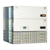
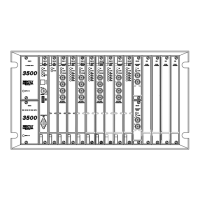
Figure 2 NE-M Components ..................................................................................................................................................................................................... 10
Figure 3 Pulsar Front Panel ...................................................................................................................................................................................................... 11
Figure 4 Millennium II Controller Front Panel .................................................................................................................................................................. 11
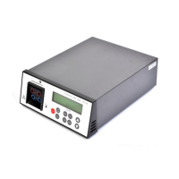
Figure 5 NE830 Display .............................................................................................................................................................................................................. 12
Figure 6 Rectifier and Converter Type Badge .................................................................................................................................................................. 12
Figure 7 Power Input Panel ...................................................................................................................................................................................................... 14
Figure 8 Battery Stand ................................................................................................................................................................................................................ 14
Figure 9 DC Distribution 4 Bullet Panels ............................................................................................................................................................................ 15
Figure 10 DC Distribution – Bolt In Panel with return bar ......................................................................................................................................... 15
Figure 11 NE-M System – 22U ................................................................................................................................................................................................ 15
Figure 12 Frame Mount Footprint ......................................................................................................................................................................................... 17
Figure 13 Battery Stand Mount .............................................................................................................................................................................................. 18
Figure 14 Mount Sub-Frame .................................................................................................................................................................................................... 18
Figure 15 Ground Frame ............................................................................................................................................................................................................ 19
Figure 16 Ground Short Frame ............................................................................................................................................................................................... 19
Figure 17 CO Ground Landing ................................................................................................................................................................................................. 20
Figure 18 Supplemental Frame .............................................................................................................................................................................................. 20
Figure 19 Interframe Bus Bars ................................................................................................................................................................................................ 21
Figure 20 L635L Dual Voltage Panel Location ................................................................................................................................................................. 22
Figure 21 Secondary Voltage Bus .......................................................................................................................................................................................... 22
Figure 22 Interframe Cables .................................................................................................................................................................................................... 24
Figure 23 Breaker Panel Alarm Connections ................................................................................................................................................................... 25
Figure 24 RPM Connections ..................................................................................................................................................................................................... 26
Figure 25 Set Frame ID on BIC 10 .......................................................................................................................................................................................... 27
Figure 26 Eco Input Panel .......................................................................................................................................................................................................... 27
Figure 27 Input Panel Screws .................................................................................................................................................................................................. 28
Figure 28 Partition Labels ......................................................................................................................................................................................................... 28
Figure 29 Partition Insert .......................................................................................................................................................................................................... 29
Figure 30 Label Input Panel ...................................................................................................................................................................................................... 29
Figure 31 Label Input Panel Cover ........................................................................................................................................................................................ 29
Figure 32 Input Power Terminal Block Positions ........................................................................................................................................................... 30
Figure 33 Rectifier / Converter and Shelf Numbering .................................................................................................................................................. 30
Figure 34 Rectifier Dual Feed Jumper Positions – ac feeds only ............................................................................................................................ 30
Figure 35 Input Conduit Locations ........................................................................................................................................................................................ 31
Figure 36 Input Jumper Dividers ........................................................................................................................................................................................... 31
Figure 37 AC Bridging Jumper ................................................................................................................................................................................................ 31
Figure 38 Input Panel Sections ............................................................................................................................................................................................... 32
Figure 39 Battery Trays .............................................................................................................................................................................................................. 33
Figure 40 Batteries in Tray – 48V........................................................................................................................................................................................... 33
Figure 41 Place Batteries........................................................................................................................................................................................................... 34
Figure 42 Battery Inter-Cell Bus Bars .................................................................................................................................................................................. 34
Figure 43 Battery Disconnect Switch .................................................................................................................................................................................. 35
Figure 44 Batt Disconnect Switch Input Bus .................................................................................................................................................................... 35
Figure 45 Battery Cable -48V .................................................................................................................................................................................................. 36
Figure 46 Battery Cable +24V ................................................................................................................................................................................................. 36
Figure 47 Battery Return Cable -48V ................................................................................................................................................................................... 37
Figure 48 Battery Return Cable +24V .................................................................................................................................................................................. 37
Figure 49 Anderson Battery Connector ............................................................................................................................................................................. 38
Figure 50 Battery Connections - Anderson ...................................................................................................................................................................... 38
Figure 51 Battery Cable Direct -48V .................................................................................................................................................................................... 39
Figure 52 Battery Cable Direct +24V ................................................................................................................................................................................... 39
Figure 53 Battery Return Cable Direct -48V ..................................................................................................................................................................... 39
Figure 54 Battery Return Cable Direct +24V .................................................................................................................................................................... 40
Figure 55 External Battery Connections ............................................................................................................................................................................ 40
Figure 56 Battery Additional Landings................................................................................................................................................................................ 40
Figure 57 Battery and Return Bus Lug Spacers .............................................................................................................................................................. 40
Figure 58 Battery Bus Labels ................................................................................................................................................................................................... 41