NE-M Installation Guide H5692448
850050111 Issue 03 August 2017 62
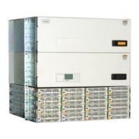
Install Converters
Repeat the above steps for converters; use converter-only slots first if provided. These are the lowest mounted shelves
and labeled “Converter Only”.
For more information on rectifiers and converters, see the Troubleshooting section.
Install Battery Voltage Temp (VT)-Probes
QS873A VT Probes can be used with or without mid-string voltage monitoring. Only one probe is required to allow the
battery slope thermal compensation function to be utilized.
Refer to the Galaxy Pulsar Plus Family Product Manual for installation instructions.
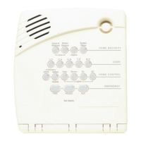
Install Aux Display (NE830A) Alarm Cable (Optional)
The optional NE830 Aux Display, when ordered separately, will require field installation. To do so, perform the following
steps:
Step Action
Is the NE830A factory installed?
Yes –no action required. Go to next section.
1
Connect and wire to field installed NE830A.
2
Install wiring per NEC and local rules for Class 3 circuits.
Note: Cable supplied with NE830A is suitable for Class 3 circuits.
3
Apply appropriate terminals (if necessary) to the cable after removing the supplied had 1/4 inch Faston ®
terminals:
Table 8 Power Connections - NE830
Pin Wire Signal Name Connect to:
1 Green Earth Ground Frame Ground
24V point to be monitored (+24V or -24V)
-48V point to be monitored (-48V only)
4 Black
Return for signals on pins 2 & 3
4
Connect and wire connection to NE830A. Alarm cable comcodes are
15ft: CC847922101, 150 ft.: CC848804765.
Figure NE830 Alarm Cable Connector
Table 9 Alarm Connections -
NE830
Pin Wire Signal Name
1 Black Common
2 Brown Open On Alarm
Alarm Cable
Connector
 Loading...