NE-M Installation Guide H5692448
850050111 Issue 03 August 2017 53
Step Action – Pulsar Plus
4
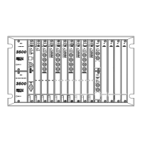
Output Alarm Connector
Connect and wire remote alarm output circuits to Connector J4. J4 is output alarm connector.
Utilize cable as necessary to obtain the desired connections to the outputs shown below.
Output Alarm Cable comcodes for J4 are: 50ft: CC848817635, 150ft: CC848817643.
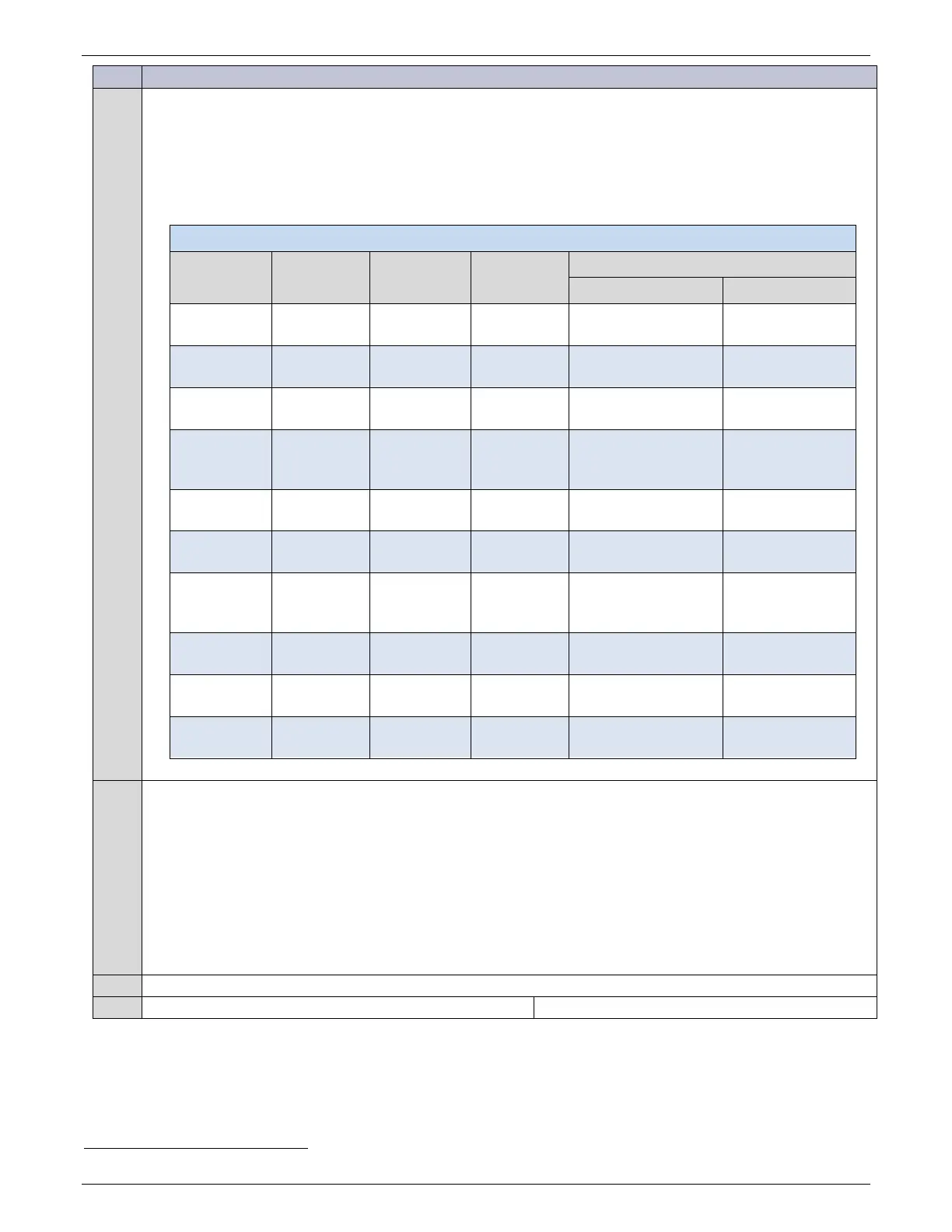
Table 6 Alarm Signals - Pulsar Plus
Pin Wire
Signal
Name
19
Pin Wire
Signal
Name
19
Defaults
Standard Eco
1 BL PCR 11 BL/BK PCR_C
PCR
(Power Critical)
2 O PMJ 12 O/BK PMJ_C
PMJ
3 G PMN 13 G/BK PMN_C
(Power Minor)
4 W UR1 14 W/BK UR1_C
(Battery on
Discharge)
5 BK UR2 15 BK/W UR2_C
VLV
(Very Low Voltage)
6 BL/W UR3 16 BL/R UR3_C
FAJ
(External Fuse Major)
7 O/R UR4 17 R UR4_C
ACF
(rectifier input AC or
DC) Fail)
Generator
Start/Stop
8 G/W UR5 18 R/G UR5_C
(Rectifier Fail)
9 W/R UR6 19 R/W UR6_C
(Multi Rectifier Fail)
10 BK/R UR7 20 R/BK UR7_C
HV
(High Voltage)
Generator
Maintenance
5
Network (LAN) Connection (Optional)
Connect to network.
The controller provides an Ethernet connection for a LAN and or Craft port connection. Connector J5 provides a
standard RJ45 shielded receptacle connection for a standard Cat-5 connection to the controller’s 10/100Base-T
port. This port has two main modes of operation: Server mode, LAN mode (Static and DCHP Client). In server
mode, the port can be used as a local Craft interface. In this mode, a local laptop can be connected through J5
and its standard web browser used to directly access the controller by typing in network address
http://192.168.2.1. A connection should never be made between the controller and LAN while the controller is in
Server mode.
Is the controller equipped with the Modem Option?
19
Relays are reconfigured for specific use for specific Eco applications.