NE-M Installation Guide H5692448
850050111 Issue 03 August 2017 29
Step Action
4
Slide Terminal Blocks and spacer to the left of the Partition
location to the left to allow installation of the PV/AC Partition.
Figure 29 Partition Insert
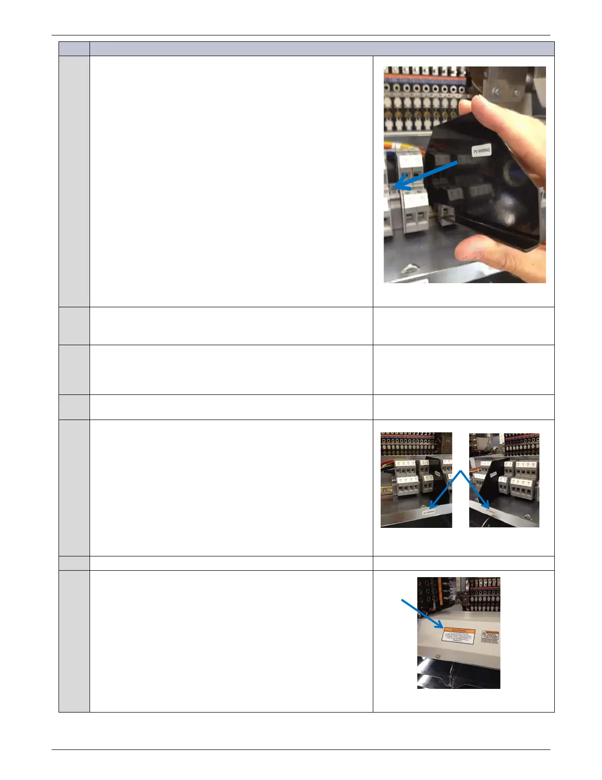
5
Install PV/AC Partition in the location specified in the site
engineering instructions.
Snap the Partition onto the DIN rail.
6
Slide the loosened Terminal Blocks and spacer block to the right
snugly against the Partition.
The Partition lower edge will be under the Terminal Block on its
left.
7
Tighten screws securing all DIN spacer blocks s to the left of the
Partition.
8
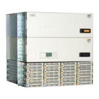
Apply labels to the Input Panel chassis.
• Place “PV Wiring” label on the left (PV) side of partition.
• Place the “AC Wiring” label on the right (AC) side of
partition.
`
Figure 30 Label Input Panel
Replace the Input Panel cover and secure fasteners.
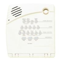
10
Apply 2 labels to Input Panel cover in any available space.
• Warning label
• Max Power-Point label
Figure 31 Label Input Panel Cover