NE-M Installation Guide H5692448
850050111 Issue 03 August 2017 32
Step Action
4
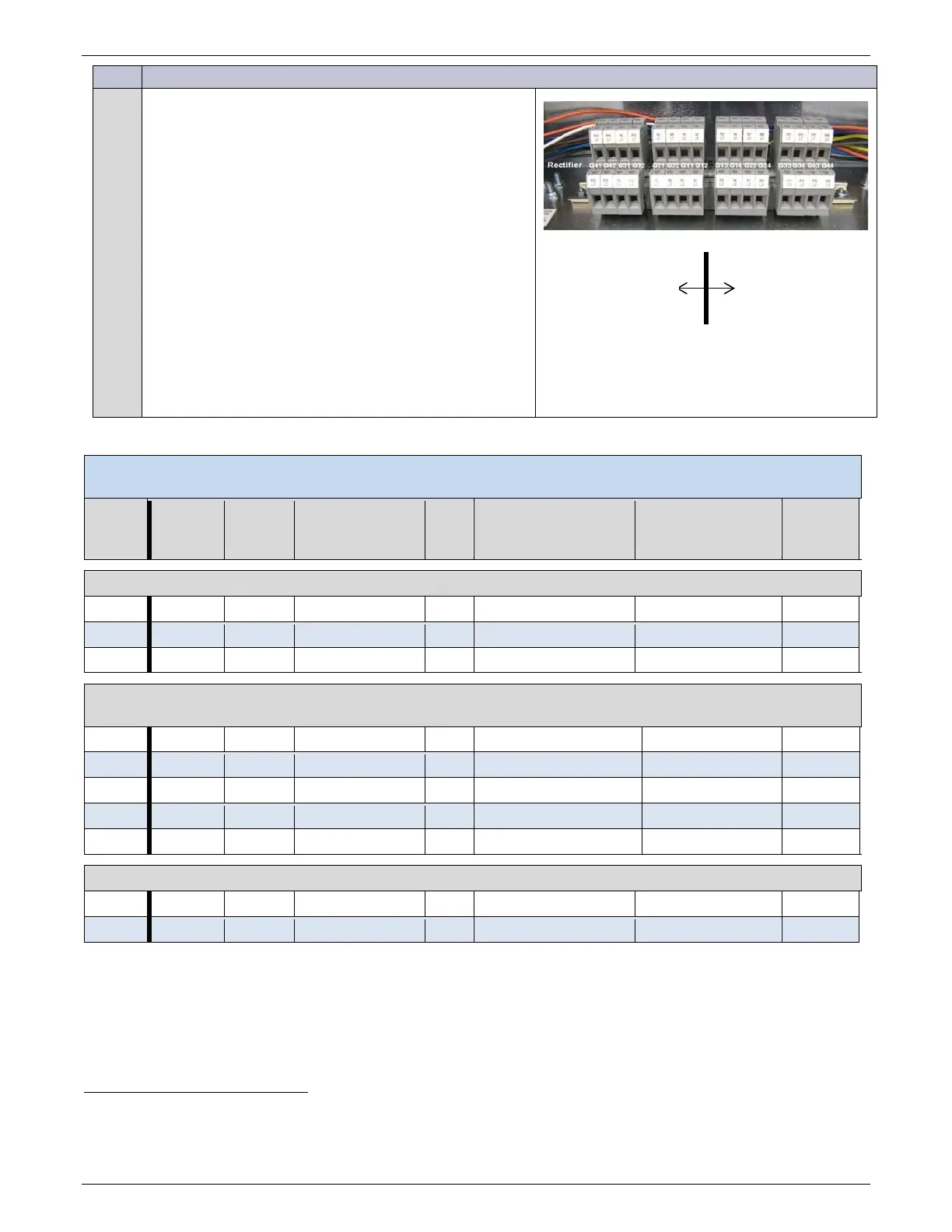
Pull and terminate input feed wires to the terminal blocks
in the Input Panel.
• ac input feeds to the AC section of the Input
Panel
• PV input feeds to the PV section of the Input
Panel
Positive PV to L1
Negative PV to L2.
Torque to 10 in-lb.
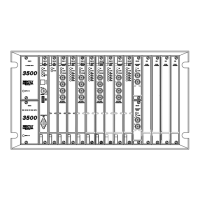
Figure 33 shows rectifier and shelf numbering.
Figure 38 Input Panel Sections
Table 2 Conduit Size - Input Feed
#
of AC
Rectifiers
per
Rectifiers
per feed
Min. External
Breaker
Wire
Gage
Minimum Conductor
Rating
15
Conductors per
Conduit
16, 17
Conduit
Size
AC Feeds NE075AC48xxxx at 200-240V~ or 200-277V~, 22A
(16)
(24)
AC Feeds NE0100AC24xxxx and NE050AC48xxxx at 200-240V~ or 200-277V~, 15A
NE055AC48xxxx at 200-240V~ or 200-277V~, 16A
(28)
PV Feeds
(28)
14
28 power units maximum in 7 power shelves maximum.
15
Based on NEC: 90°C Conductor, 45°C Ambient, and Number of Wires in Conduit.
16
Includes 1 ground per conduit - not considered in derating.
17
AC and PV feeds must be in separate conduits.
Eco only
PV Section
ac Section
NE-M Eco only