NE-M Installation Guide H5692448
850050111 Issue 03 August 2017 44
GMT6A Style Fuse Module (bullet)
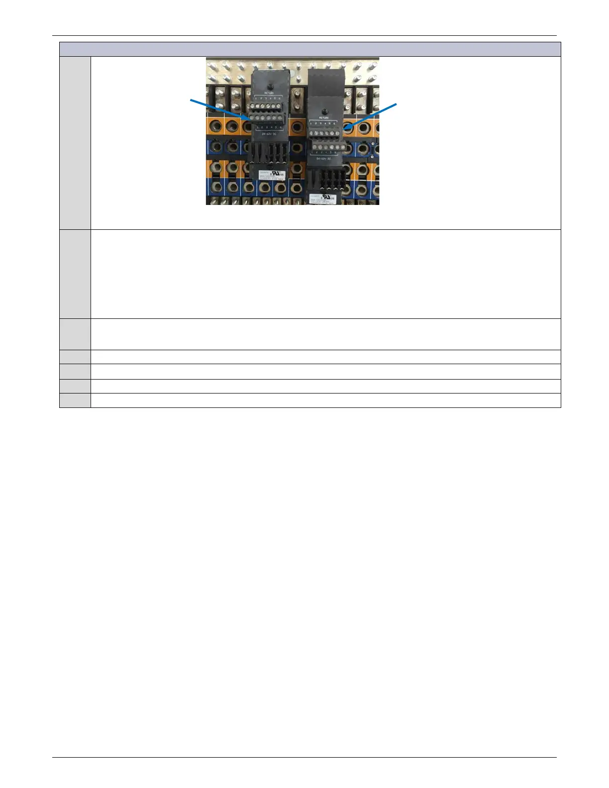
Figure 61 GMT Fuse Module
1
GMT6A Module must be installed before load connection is made.
Install GMT Module into specified bullet positions: -48V (Blue) or +24V (Orange).
Secure GMT Module Return bus bar to the distribution panel Return bus bar with provided nuts.
Note: Return bus on GMT Module is adjustable for -48V or for +24V installation – see GMT Module Installation
Guide.
Torque to 65 in-lb - 7/16” socket.
2
Strip Load and Load Return wires 3/8” and secure in the GMT module terminal block.
Torque to 13 in-lb - screw driver.
3
Dress and wire tie with service loop to provide strain relief.
Verify voltage and polarity between the Return bus and each distribution input bus using a voltmeter.
Verify wiring polarity at the input of the load equipment.
Do not install load fuses until the load equipment is ready to be energized.
GMT Module
in +24V positions
in -48V positions
Max Wire 12 AWG
Max Module Current 57.6A