110 GE INFORMATION D20E ETHERNET I/O MODULE INSTRUCTION MANUAL
CHAPTER 9: USING THE D20E MODULE
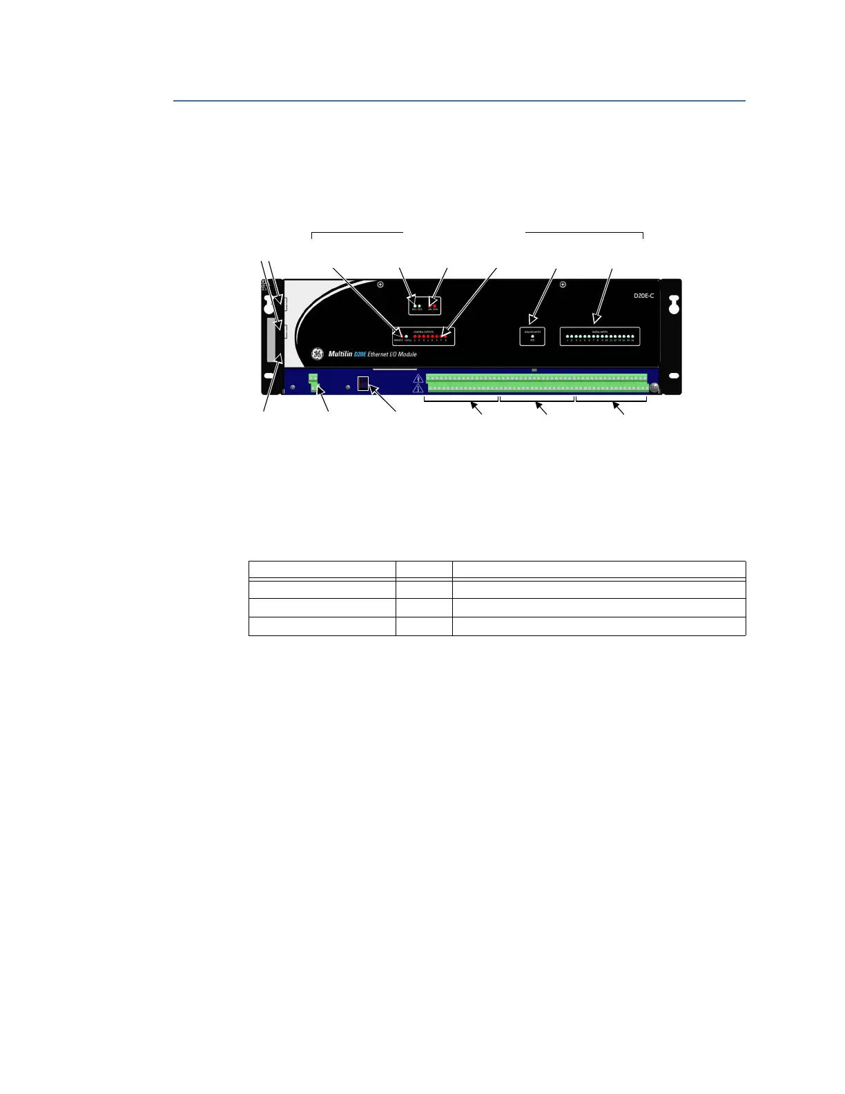
D20E-C module front panel
The location of the D20E-C module front panel key elements and connectors is shown in
Figure 29.
Figure 29: D20E-C module front panel elements
D20E-C LEDs
The D20E-C module LEDs are listed in Table 37.
Table 37: D20E-C status LEDs
Remote/local switch
The remote/local switch (S1) operation is described in section: Module remote/local switch
on page 105.
D20E-C connectors
For information on Terminal Block 2 (TB2) connector assignments for the D20E-C module,
see
D20E-C combination inputs and outputs module on page 97.
TB1 Power
input
Remote/Local
switch
USB 2.0
port
TB2 Digital
Outputs
TB2 Analog
Inputs
TB2 Digital
Inputs
LAN ports
Remote/
Local
LED Status indicators
Power
source
System
status
Control
output
Analog
inputs
Digital
inputs
LED Indicator Color Description
ANALOG INPUTS - ADC Blue Analog input digital conversion process
DIGITAL INPUT 1 to 16 Blue Digital input 1 to 16 ON
CONTROL OUTPUT 1 to 8 Red Control output selected 1 to 8 ON