60 GE INFORMATION D20E ETHERNET I/O MODULE INSTRUCTION MANUAL
CHAPTER 3: CONFIGURING THE D20E FIRMWARE
Counter points
The Digital Input points in the D20E-S and D20E-C modules can be configured as counter
type points. When a digital input is configured as a counter point, each digital status
change event is accumulated and reported as a counter value.
Configure counter
points
A Digital Input and a Counter cannot be assigned to the same contact.
To configure a counter point:
1. Remove a Digital Input from the point list.
2. Add the Counter to the point list.
If a Digital Input and Counter are configured to share the same contact, an error message
appears and a sync with the D20E is not allowed.
Counter type A Digital Input point can be configured with the counter types listed in Table 8.
Table 8: Counter type descriptions
Dual point counter The states of a dual point counter are listed in Table 9.
Table 9: Dual point counter - states
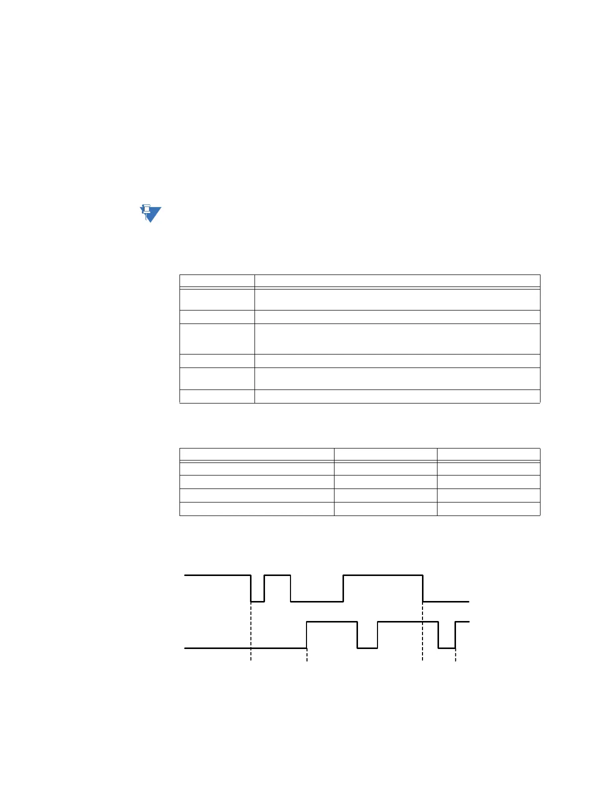
Figure 10 shows the indicator states triggered by Point 1 and Point 2. The first transition is
from Point 1, then the opposite transition from Point 2, and so on.
Figure 10: Dual point counter - state changes
Counter type Description
Binary Single input counter that accumulates a specified polarity transition or state
change.
Binary Frozen Binary counter in conjunction with a protocol freeze command.
Form C This is a two-input counter, the same as a standard KYZ counter. When any
complimentary state change occurs simultaneously on the two inputs, the
counter increases in value on the specified high or low polarity transition.
Form C Frozen Form C counter in conjunction with a protocol freeze command.
Dual Point This is a two-input switch or breaker operation counter. See figure for
functionality.
Dual Point Frozen DP counter in conjunction with a protocol freeze command.
Number of possible indicator states State of point 1 State of point 2
110
201
311
400
Point 1
Point 2
Counts 1 2 3 4