106 GE INFORMATION D20E ETHERNET I/O MODULE INSTRUCTION MANUAL
CHAPTER 9: USING THE D20E MODULE
TB1 connectors The TB1 terminal block connector assignments are indicated in Table 33.
Table 33: TB1 connectors
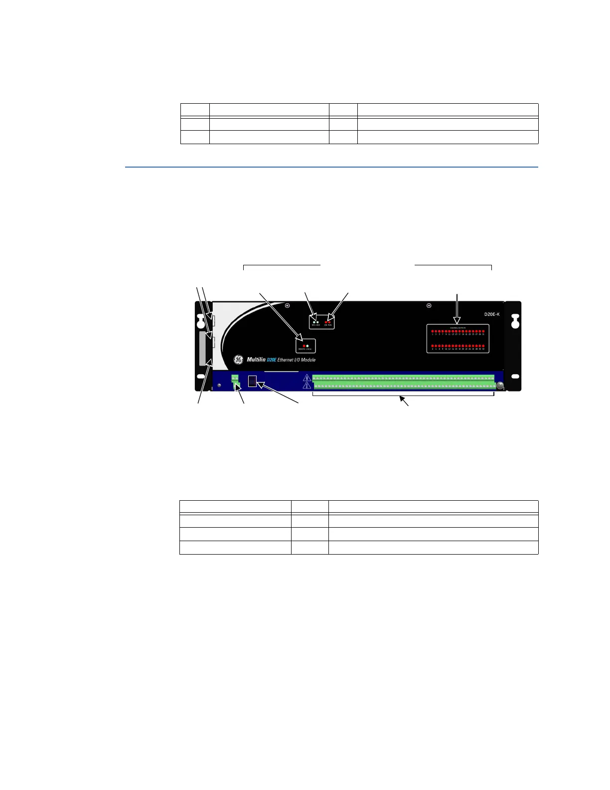
D20E-K module front panel
The location of the D20E-K module front panel key elements and connectors is shown in
Figure 26.
Figure 26: D20E-K module front panel elements
D20E-K LEDs
The D20E-K module LEDs are listed in Table 34.
Table 34: D20E control output status LEDs
Remote/local switch
The remote/local switch (S1) operation is described in section: Module remote/local switch
on page 105.
D20E-K connectors
For information on Terminal Block 2 (TB2) connector assignments for the D20E-K module,
see
D20E-K control outputs module on page 89.
TB1 Description TB1 Description
1 Positive External Supply 1 (+) 3 Positive Redundant External Supply 2 (+)
2 Negative External Supply 1 (‒) 4 Negative Redundant External Supply 2 (‒)
TB1 Power
input
Remote/Local
switch
USB 2.0
port
TB2 Digital
Outputs
LAN ports
Remote/
Local
LED Status indicators
Power
source
System
status
Control
output
LED Indicator Color Description
REMOTE Red Control outputs enabled
LOCAL Blue Control outputs disabled
CONTROL OUTPUT 1 to 32 Red Control output selected 1 to 32 ON