108 GE INFORMATION D20E ETHERNET I/O MODULE INSTRUCTION MANUAL
CHAPTER 9: USING THE D20E MODULE
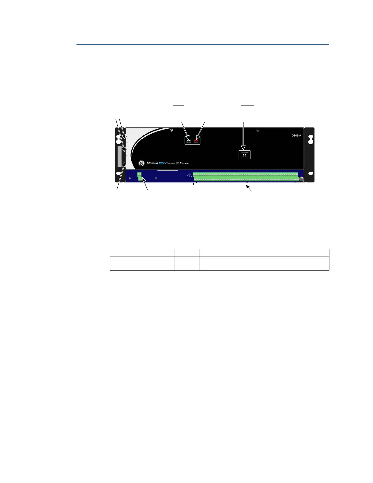
D20E-A module front panel
The location of the D20E-A module front panel key elements and connectors is shown in
Figure 27.
Figure 27: D20E-A module front panel elements
D20E-A LEDs
The D20E-A module LEDs are listed in Table 35.
Table 35: D20E analog inputs status LEDs
D20E-A connectors
For information on Terminal Block 2 (TB2) connector assignments for the D20E-A module,
see
D20E-A analog inputs module on page 87.
TB1 Power
input
USB 2.0
port
TB2 Analog
Inputs
LAN ports
LED Status indicators
System
status
Analog
inputs
Power
source
LED Indicator Color Description
ANALOG INPUTS - 1 and 2 Blue Analog Digital Conversion (ADC) processes 1 and 2 for
analog inputs.