CHAPTER 11: SERVICING THE D20E MODULE HARDWARE
D20E ETHERNET I/O MODULE INSTRUCTION MANUAL GE INFORMATION 117
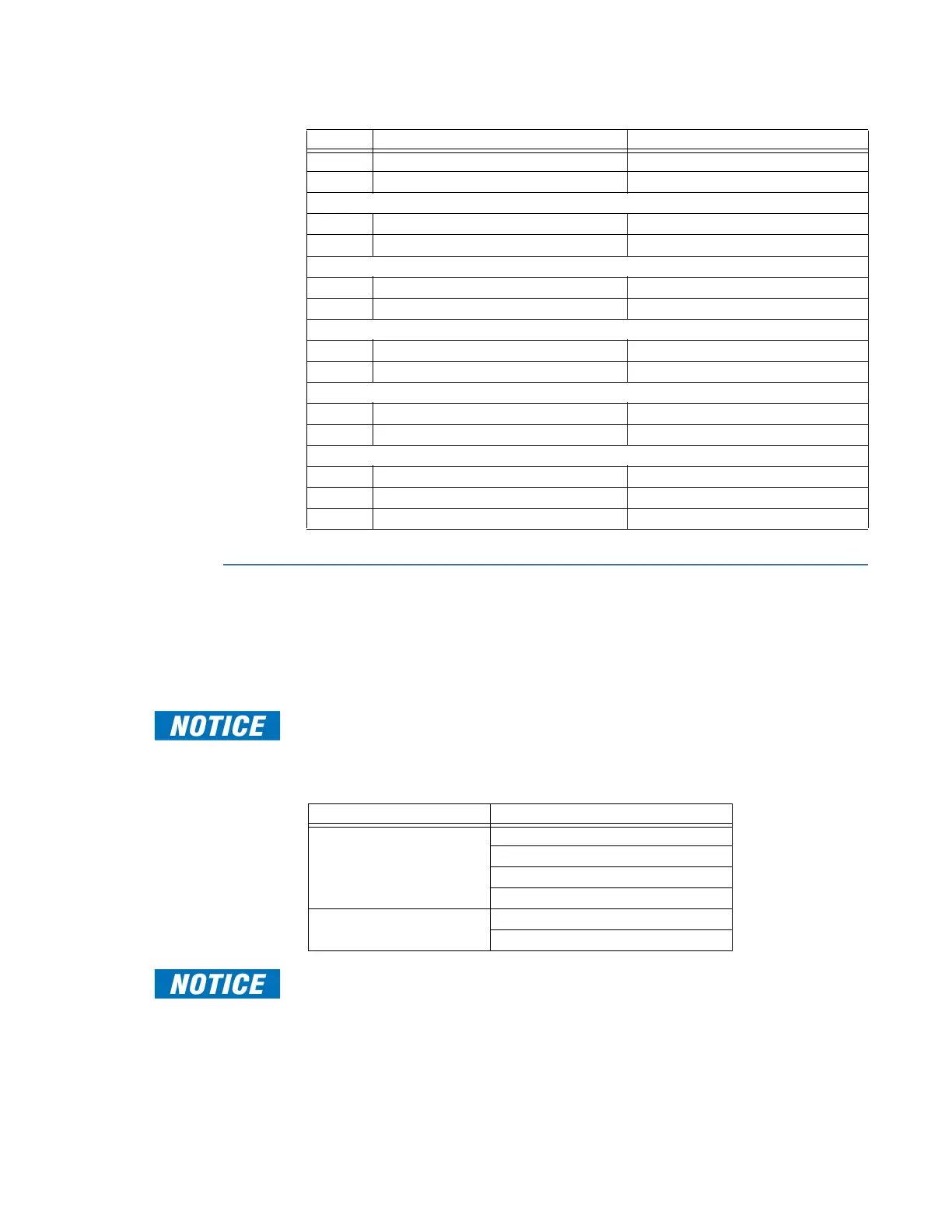
Table 38: Fuse ratings
DIP switch settings
The D20E modules have two DIP switches on the internal Logic board assembly:
• CFG RESET and
• WDI.
These DIP switches are factory set and must not be changed.
Table 39 specifies the DIP switch settings which must be in place in order for the D20E
module to operate correctly.
Table 39: DIP switch settings - required
Do not press the CPU RST or the K10 Reset push-button switches. Pressing either of these
switches causes the D20E module to reset or restart.
Fuse # Descriptions Fuse Type
F1 DC+ Power Protection T500mA 250V (time-delay or slow-blow)
F2 DC‒ Power Protection T500mA 250V (time-delay or slow-blow)
D20E-K module
F3 Control Output +/‒ Supply 2A 250V (fast-acting)
F4 Control Output ‒/+ Supply 2A 250V (fast-acting)
D20E-K (DB25) interface
F3 Control Output +/‒ Supply 0.5A 250V (fast-acting)
F4 Control Output ‒/+ Supply 0.5A 250V (fast-acting)
D20E-S module
F3 Digital Input +/‒ Supply 0.5A 250V (fast-acting)
F4 Digital Input ‒/+ Supply 0.5A 250V (fast-acting)
D20E-A module
F3 Analog Input + Loop Supply 1A 250V (fast-acting)
F4 Analog Input ‒ Loop Supply 1A 250V (fast-acting)
D20E-C module
F3 Digital Input and Control Output +/‒ Supply 2A 250V (fast-acting)
F4 Digital Input and Control Output ‒/+ Supply 2A 250V (fast-acting)
F5 Control Output Supply 2A 250V (fast-acting)
DIP switch Required switch position
CFG RESET 1-OFF
2-OFF
3-OFF
4-OFF
WDI 1-ON
2-OFF