CHAPTER 7: CONNECTING FIELD WIRING TO THE D20E MODULE
D20E ETHERNET I/O MODULE INSTRUCTION MANUAL GE INFORMATION 99
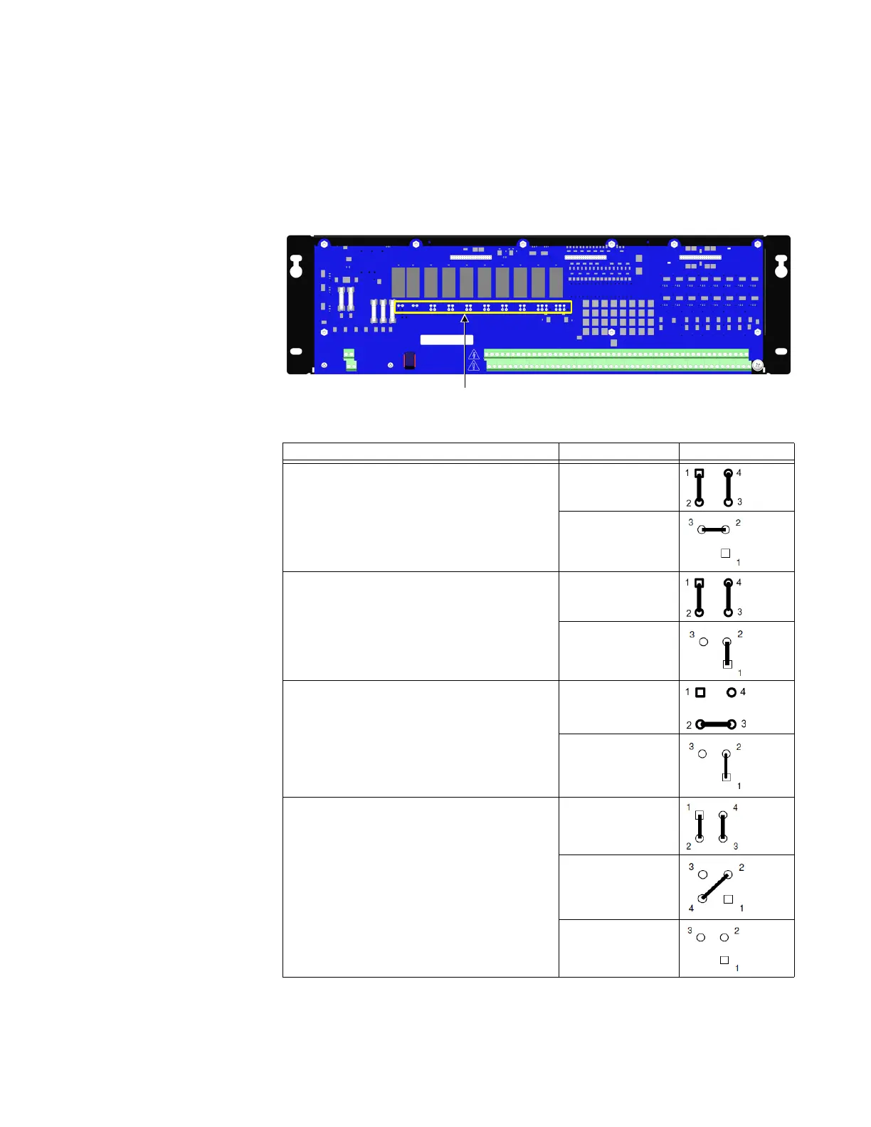
D20E-C module control outputs
The D20E-C has 10 on-board relays that are factory configured into a variety of output
types; see
Table 27 for connection details.
See Table 26 for termination block details.
The W1 to W12 jumpers are located on the D20E-K as shown in Figure 24.
Figure 24: D20E-C module - jumper locations
Table 27: D20E-C - summary of control types and jumper setting positions
Control Type Jumper and Supply Setting
Trip/Close
Trip/Close supply TB2-2(+/‒) and TB2-51(‒/+)
LOCAL/REMOTE Switch supply: TB2-1(+/‒) and TB2-
51(‒/+)
W3-W9, W11
W1 and W2
DPST
Control Output supply TB2-1(+) and TB2-51(‒)
W3-W9, W11
W1 and W2
Form C
LOCAL/REMOTE Switch supply: TB2-1(+/‒) and
TB2-51(‒/+)
W3-W9, W11
W10 and W12
Raise/Lower
R/L supply TB2-2 (+/‒) and TB2-51 (‒/+)
LOCAL/REMOTE Switch supply: TB2-1(+/‒) and
TB2-51(‒/+)
W3-W9, W11
W1
W2