CHAPTER 9: USING THE D20E MODULE
D20E ETHERNET I/O MODULE INSTRUCTION MANUAL GE INFORMATION 105
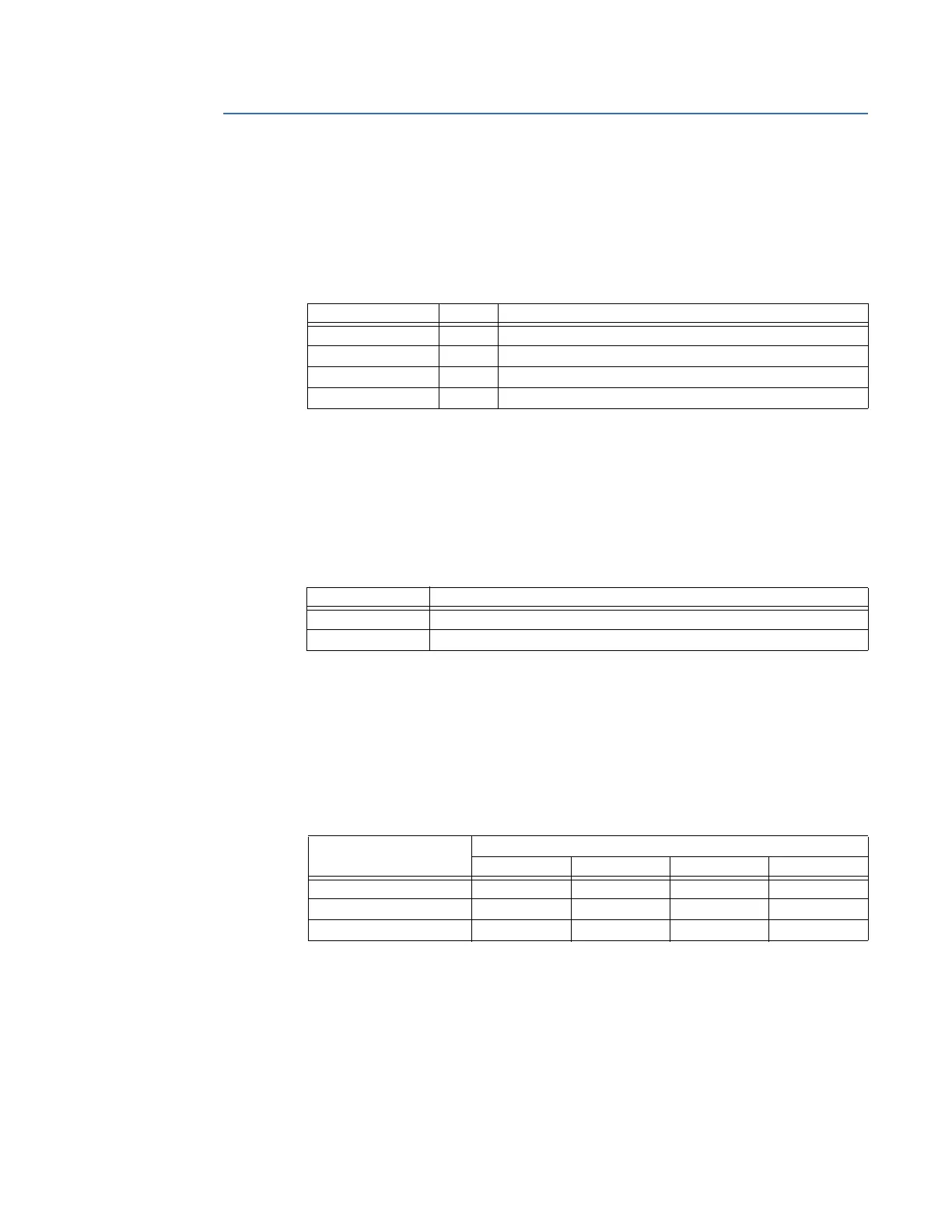
Front panel
LEDs common to all D20E module types
The Power Supply LEDs on the D20E module front panel indicate the power supply and
operation status (see
Table 30).
These LEDs apply to all D20E modules.
Table 30: D20E power supply and operation status LEDs
Module remote/local switch
The remote/local switch (S1) operation is described in Table 31.
This switch applies to the following modules:
• D20E-K
• D20E-C
Table 31: Remote/Local switch
See section: Remote/Local switch on page 90 for details.
Terminal block connector summary
TB2 connectors The number of available inputs/outputs on the TB2 terminal block for each D20E module
type is indicated in
Table 32.
Table 32: TB2 connectors - input/output summary
For connection details, see chapter: Connecting Field Wiring to the D20E Module on page
87.
LED Indicator Color Description
DC1 Blue DC1 power supply input 1 is present
DC2 Blue DC2 power supply input 2 is present
ON Red D20E power supply output (5 VDC/3.3 VDC) is present
RUN Red CPU operating properly, 1sec ON/OFF after restart initialization
Switch label Description
LOCAL Select local mode to disable the operation of control outputs.
REMOTE Select remote to enable the operation of control outputs.
Field connection type Number of I/O connections on module type
D20E-K D20E-A D20E-S D20E-C
Digital Outputs (control) 32 8
Analog Inputs 32 16
Digital Inputs (status) 64 16