D20E ETHERNET I/O MODULE INSTRUCTION MANUAL GE INFORMATION 87
D20E Ethernet I/O Module
Chapter 7: Connecting Field Wiring
to the D20E Module
Connecting Field Wiring to the D20E Module
This chapter describes the I/O connection for each type of D20E module:
• D20E-A analog inputs module on page 87
• D20E-K control outputs module on page 89
• D20E-S digital inputs module on page 95
• D20E-C combination inputs and outputs module on page 97
Field wiring is connected to the D20E modules at terminal block TB2.
D20E-A analog inputs module
The D20E-A supports up to 32 differential analog inputs. The field terminations for analog
inputs are provided by TB2-1 to TB2-48 and TB2-51 to TB2-98 (See
Table 21 for details).
One shield termination is allocated for each input.
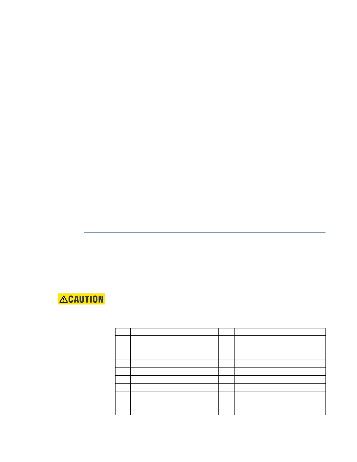
Table 21 lists the TB2 terminal block connection assignments for the D20E-A.
The wiring connected to terminal block TB2 must not have exposed accessible
conductors.
The wire and cable connected must have at least a +80 °C temperature rating.
Table 21: D20E-A - analog input module terminal block assignments
TB2 Descriptions TB2 Descriptions
1 Analog Input 1+ 51 Analog Input 1‒
2 Shield/Screen Ground 52 Shield/Screen Ground
3 Analog Input 2+ 53 Analog Input 2‒
4 Analog Input 3+ 54 Analog Input 3‒
5 Shield/Screen Ground 55 Shield/Screen Ground
6 Analog Input 4+ 56 Analog Input 4‒
7 Analog Input 5+ 57 Analog Input 5‒
8 Shield/Screen Ground 58 Shield/Screen Ground
9 Analog Input 6+ 59 Analog Input 6‒
10 Analog Input 7+ 60 Analog Input 7‒