CHAPTER 7: CONNECTING FIELD WIRING TO THE D20E MODULE
D20E ETHERNET I/O MODULE INSTRUCTION MANUAL GE INFORMATION 89
D20E-K control outputs module
The D20E-K has 34 on-board relays that are factory configured into a variety of output
types; see
Table 22 for connection details.
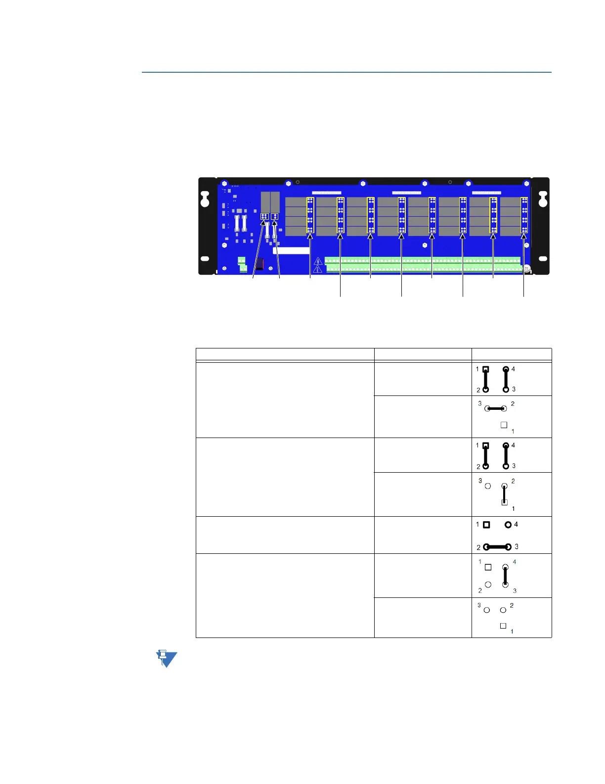
The W1, W2 to W5, and W7-W34 jumpers are located on the D20E-K as shown in Figure 17.
Figure 17: D20E-K module - jumper locations
See Table 23 for terminal block connection details.
Table 22: D20E-K - summary of control types and jumper setting positions
See Table 24 (and Notes) for D20E-K (DB25) Interface jumper settings and terminal block
connections.
Control Type Jumper and Supply Setting
Trip/Close
Trip/Close supply: TB2-54(+/‒) and TB2-1(‒/+)
Jumper W1: 1 & 4, 2 & 3
W2-W5, W7-W34
W6
DPST
DPST supply: TB2-54(+/‒) and TB2-1(‒/+)
Jumper W1: 1 and 2
W2-W5, W7-W34
W6
Form C
REMOTE/LOCAL switch supply: TB2-54(+) and
TB2-1(‒)
W2-W5, W7-W34
Raise/Lower
Raise/Lower supply: TB2-54(+/‒) and TB2-1(‒/+)
Jumper W1: 1 & 2
W2-W5, W7-W34
W6
Jumper
W6
Jumper
W1
Jumpers
W2 to W5
Jumpers
W15 to W18
Jumpers
W19 to W22
Jumpers
W23 to W26
Jumpers
W27 to W30
Jumpers
W31 to W34
Jumpers
W6 to W9
Jumpers
W10 to W14