GE COMPANY
DIRECTION 5472001-1EN, REVISION 6OPTIMA CT680 SERIES AND OPTIMA CT670 INSTALLATION MANUAL
Page 134 Section 1.0 - System Continuity (Mechanical Contractor)
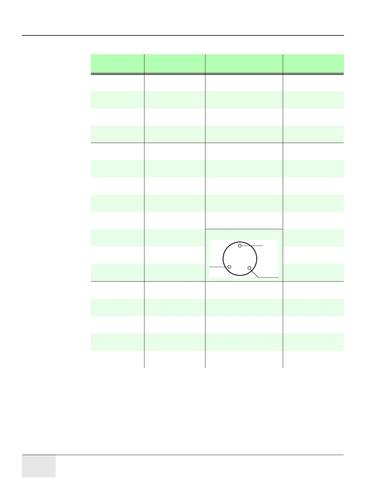
6.) Verify that less than 1 ohm of resistance exists between the following connections:
FROM SIGNAL NAME
(COLOR)
TO
PDU TS2-1 +HVDC
(Red)
Gantry HV Power Pan
TS1-1
Check box when
complete
PDU TS2-2 HVDC Ground
(Green/Yellow)
Gantry Power Pan Chassis Check box when
complete
PDU TS2-3 -HVDC
(Black)
Gantry HV Power Pan
TS1-2
Check box when
complete
PDU Ground Bus HVDC shield Gantry HVDC cable shield Check box when
complete
PDU TS3-1 Axial drive 440vac
(Black)
Gantry HV Power Pan
TS2-1
Check box when
complete
PDU TS3-2 Axial drive 440vac
(Red)
Gantry HV Power Pan
TS2-2
Check box when
complete
PDU TS3-3 Axial drive 440vac
(Orange)
Gantry HV Power Pan
TS2-3
Check box when
complete
PDU TS3-4 Axial drive ground
(Green/Yellow)
Gantry Power Pan Chassis Check box when
complete
PDU Ground Bus Axial drive shield Gantry 440 VAC cable
shield
Check box when
complete
PDU TS5-1 120vac Phase A
(Brown)
Console Power Plug: Check box when
complete
PDU TS5-2 120vac Neutral
(Light Blue)
Check box when
complete
PDU TS5-3 Ground
(Green/Yellow)
Check box when
complete
PDU TS5-4 120vac Phase A
(Black)
Gantry LV Power Pan TS4-
1
Check box when
complete
PDU TS5-5 120vac Phase B
(Red)
Gantry LV Power Pan TS4-
2
Check box when
complete
PDU TS5-6 120vac Phase C
(Orange)
Gantry LV Power Pan TS4-
3
Check box when
complete
PDU TS5-7 120vac Neutral
(Light Blue)
Gantry LV Power Pan TS4-
4
Check box when
complete
PDU TS5-8 Ground
(Green/Yellow)
Gantry Power Pan Chassis Check box when
complete
Table 3-2 Resistance Verification Points
BLU
GRN/YLW
BRN
W
G

 Loading...


