GE COMPANY
DIRECTION 5472001-1EN, REVISION 6OPTIMA CT680 SERIES AND OPTIMA CT670 INSTALLATION MANUAL
Page 136 Section 1.0 - System Continuity (Mechanical Contractor)
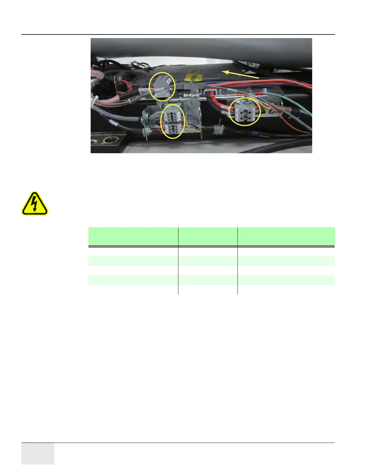
Figure 3-2 Gantry Power Pan
WARNING TURN OFF ALL PDU CIRCUIT BREAKERS.
7.) Set an ohmmeter to the lowest scale. Check between the following points for shorts to ground.
Verify no continuity exists between the following points:
8.) Leave the metal cover off the PDU A3 input power panel until you complete the checks in the
next section.
HVAC 120V
Power Pan
TS1
TS5
TS4
TS2
Table 3-3 No Continuity Verification Points
FROM PDU TO A1
BREAKER BOX
TS2-1 (+HVDC) (Red) vault ground Check box when complete
TS2-3 (-HVDC) (Black) vault ground Check box when complete
TS3-1 (440vac output) (Black) vault ground Check box when complete
TS3-2 (440vac output) (Red) vault ground Check box when complete
TS3-3 (440vac output) (Orange) vault ground Check box when complete

 Loading...


