Chapter 4. Ladder Diagram (LD) Programming
GFK-2950C February 2018 193
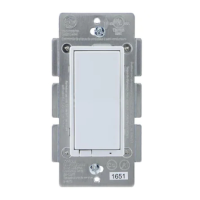
Example1 for ADD
The first example is a failed attempt to create a counter
circuit that would count the number of times switch
%I00001 closes. The running total is stored in register
%R00002. The intent of this design is that when %I0001
closes, the ADD instruction should add one to the value in
%R00002 and place the new value right back into %R0002.
The problem with this design is that the ADD instruction
executes once every PLC scan while %I0001 is closed. For
example, if %I0001 stays closed for five scans, the output
increments five times, even though %I00001 only closed
once during that period.
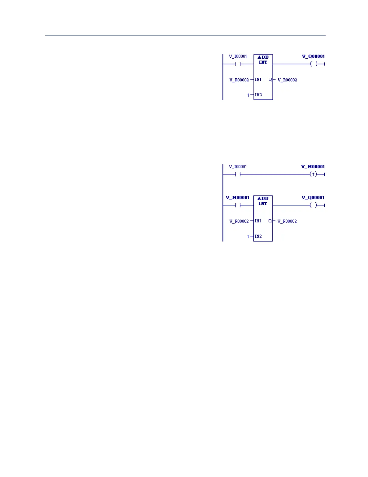
To correct the above problem, the enable input to the ADD
instruction should come from a transition (
one-shot
) coil, as
shown below. In the improved circuit, the %I0001 input
switch controls a transition coil, %M0001, whose contact
turns on the enable input of the ADD function for only one
scan each time contact %I00001 closes. In order for the
%M00001 contact to close again, contact %I0001 has to
open and close again.
Note: If IN1 and/or IN2 is NaN (Not a Number), ADD_REAL
passes no power flow.
 Loading...