80209C_MHW_850-1650-1850_02-2020_ENG_pag. 141
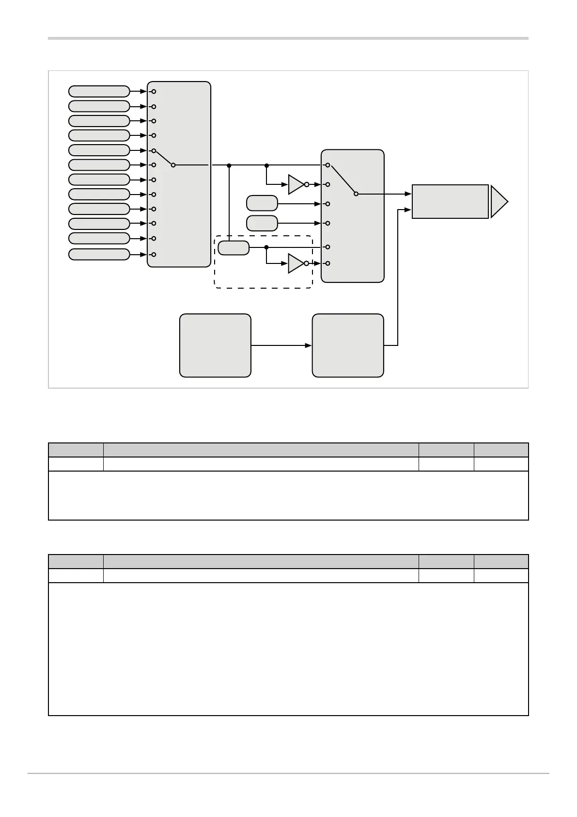
4.19.1. Functional diagram
4.19.2. OU.AN.N - Selecting the output
Acronym Scrolling message Submenu Attributes
OU.AN.N ANALOG OUTPUT NUMBER OUT.AN R W
The parameter shows and sets the identifying number of the output to be configured.
Unit of measurement: Number
Options: 1...2
4.19.3. STAT - Defining the state of the analog output
Acronym Scrolling message Submenu Attributes
StAt OUT.AN.1 (o OUT.AN.2) ANALOG OUTPUT STATUS OUT.AN R W
The parameter shows and sets the state of analog retransmission output A1 or A2.
The active direct output corresponds to minimum with the minimum output value in voltage or current.
The active inverse output corresponds to minimum with the maximum output value in voltage or current.
The outputs can be forced so that they are always on or off.
Unit of measurement: -
Options: DIREC = Direct output
INVRS = Inverse output
OFF = Forced output inactive (minimum voltage or current value)
ON = Forced output active (maximum voltage or current value)
DI.PWM = Direct output with partialisation of ON/OFF and cycle time CY.TIM
IN.PWM = Inverse output with partialisation of ON/OFF and cycle time CY.TIM
GESTIONE PWM
with analog levels
Function
FUNC pag.
142
NONE
HEAT1/HEAT2
COOL1/COOL2
IN1/IN2/IN3
PV1/PV2
SSP1/SSP2
SETP1/SETP2
DEVI1/DEVI2
SLV.S1/SLV.S2
SERIA
MASTER
H+C1/H+C2
Probe type
TYPE pag. 142
Scale limit
LO.SCL page 143
HI.SCL page 143
OFF
ON
Definition
state
STAT page 141
Analog output
state
OUT.Ax page
Analog output
CY.TIM