80209C_MHW_850-1650-1850_20-2020_ENG_pag. 39
Potentiometer VP1 or
transmitter VT2 supply
12
11
10
9
8
7
37
38
39
40
41
42
6
5
4
3
2
1
43
44
45
46
47
48
36
35
34
33
32
31
30
29
28
27
26
25
12
11
10
9
8
7
37
38
39
40
41
42
6
5
4
3
2
1
43
44
45
46
47
48
36
35
34
33
32
31
30
29
28
27
26
25
5
28
VP1 o VT2
27
26
25
+
-
VP1 = 1 VDC ±1%, max 30 mA
[with option auxiliary input = 2]
VT2 = 24 VDC ±10%, max 30 mA
[with option auxiliary input = 3]
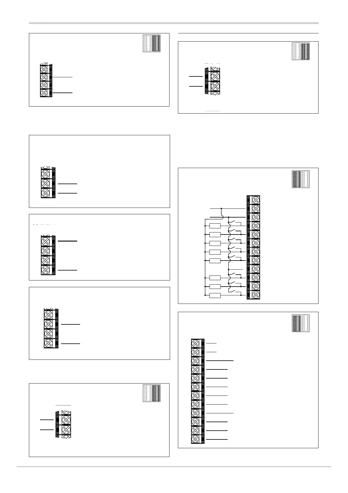
2.5.9. THIRD ANALOGUE INPUT (AUX2)
High impedance linear input (V)
[with third input option (H) = 3]
36
36
35
34
+
-
Linear input with direct voltage
0...1V Ri>100MΩ
0…1.2V Ri>100MΩ
0…2.4V Ri>100MΩ
Linear input (V/I) [with third input option (H) = 3]
35
36
35
34
33
+
-
Linear input with direct voltage and current
0…1V / 0…5V / 0…10V Ri>400kΩ
0…20mA / 4…20mA Ri=50Ω
VP2 potentiometer power supply
[VP2 = 1 VDC +- 1%, max 30mA]
36
35
34
33
+
VP2
-
2.5.10. Analog outputs
Analog outputs A1
12
11
10
9
8
7
37
38
39
40
41
42
6
5
4
3
2
1
43
44
45
46
47
48
36
35
34
33
32
31
30
29
28
27
26
25
12
11
10
9
8
7
37
38
39
40
41
42
6
5
4
3
2
1
43
44
45
46
47
48
36
35
34
33
32
31
30
29
28
27
26
25
8
30
29
28
25
-
+
0...10 V, max 20 mA Rout > 500 Ω
0...20 mA / 4...20 mA Rout < 500 Ω
Analog outputs A2
12
11
10
9
8
7
37
38
39
40
41
42
6
5
4
3
2
1
43
44
45
46
47
48
36
35
34
33
32
31
30
29
28
27
26
25
12
11
10
9
8
7
37
38
39
40
41
42
6
5
4
3
2
1
43
44
45
46
47
48
36
35
34
33
32
31
30
29
28
27
26
25
32
31
28
25
-
+
0...10 V, max 20 mA Rout > 500 Ω
0...20 mA / 4...20 mA Rout < 500 Ω
2.5.11. Connections with option optional
I/O (N) =10, 01, 11
Characteristics of optional inputs and outputs are defined
when the controller is ordered.
8 Inputs / Digital outputs (PNP)
[with option I/O = 10, 11]
12
11
10
9
8
7
37
38
39
40
41
42
6
5
4
3
2
1
43
44
45
46
47
48
36
35
34
33
32
31
30
29
28
27
26
25
12
11
10
9
8
7
37
38
39
40
41
42
6
5
4
3
2
1
43
44
45
46
47
48
36
35
34
33
32
31
30
29
28
27
26
25
43
42
41
40
39
38
37
44
45
46
47
48
LOAD
LOAD
LOAD
LOAD
LOAD
LOAD
LOAD
LOAD
External power supply
24 VDC ±25%, max 27W
OUT 6
OUT 13
OUT 7
OUT 8
OUT 9
OUT 10
OUT 11
OUT 12
IN 6
IN 13
IN 7
IN 8
IN 9
IN 10
IN 11
IN 12
GND
+
PNP digital inputs
24 V,
max 5 mA
PNP digital outputs
24 V,
max 100 mA
8 Relay
[with option I/O = 01, 11]
12
11
10
9
8
7
37
38
39
40
41
42
6
5
4
3
2
1
43
44
45
46
47
48
36
35
34
33
32
31
30
29
28
27
26
25
12
11
10
9
8
7
37
38
39
40
41
42
6
5
4
3
2
1
43
44
45
46
47
48
36
35
34
33
32
31
30
29
28
27
26
25
6
7
8
9
10
11
12
5
4
3
2
1
GND
+
OUT 14
External power supply
24 VDC ±25%, max 3,5W
OUT 21
OUT 15
NO
NO
NO
NO
NO
NO
NO
NO
OUT 16
OUT 17
OUT 18
OUT 19
COM 14...18
COM 19...21
OUT 20
Relay 5A (3A for
certification UL),
250VAC