After filter pressure monitoring MagicControl 4.0 (CM40)
Typical characteristics
– Filter monitoring (pressure switch) with two channels
– The following volume flows or fan Δp with two pressure switches
each are monitored:
• Volume flow operating point
• Volume flow alarm
• Volume flow ATEX: Stop powder
– Two additional differential pressure monitors transmit the pressure of
the filter system to the CM40.
– There are no more pressure gages in or on the cabinet. Everything
is displayed on the MagicControl CM40 screen.
– Only a main power supply is required as a power supply:
• The ICS filter cabinet contains a fuse to protect the power supply
– Cartridge cleaning is no longer time-controlled, but pressure-
controlled:
▪ As soon as the cartridge resistance exceeds a pre-set value, the
cleaning sequence begins, with all filter cartridges being cleaned
at least every hour.
– Two different control cabinet types:
▪ Star-delta control version: OptiControl ICS08
▪ FC operation version: OptiControl ICS09
Description of the pressure switches
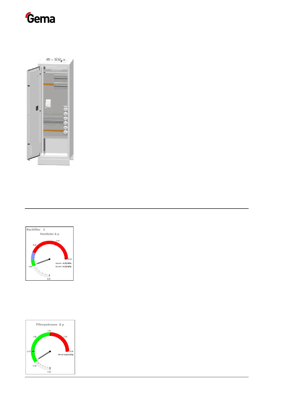
315 B1 differential pressure monitor Fan Δp
– The differential pressure monitor measures the current differential
pressure of the fan.
– The pressure is displayed on the CM40 control unit at Fan Δp:
Actual value 1.
– The pressure display at Fan Δp shows this value.
315 B3 differential pressure monitor Fan Δp
– The differential pressure monitor measures the current differential
pressure of the fan.
– The pressure is displayed on the CM40 control unit at Fan Δp:
Actual value 2
316 B1 differential pressure monitor Filter cartridges Δp
– The differential pressure monitor measures the actual differential
pressure of the filter cartridges (filter resistance).
– The pressure is displayed on the CM40 control at Filter cartridges
Δp: Actual value.