- 60 -
(red)and GND
of the body
Between GND
wire(black)and
GND of the body
With wiring
Between charging
coil(white) and
the GND of the
body
There is resistance in
the magnetor coil
Between light
wire (green/red)
and the GND
(plug of resistor,
auto side starter
plug, inspect at
OFF position after
the removing of
lighting switch
There is resistance in
the magnetor coil
1.5.2 Voltage and current adjustor
inspection
When the main wiring is completely normal, check
the contact of the adjustor’s plug, and measure the resistance value between the terminals of the adjustor.
* Note
• When checking the metal parts, your
finger should not contact test bar of the
multimeter.
•Different multimeter will show
differently, so use the same multimeter
while checking.
Replace the voltage adjustor when the resistance value between the terminals is abnormal.
1.6 Magnetor charging coil
*Note
Check the magnetor charging coil on the
engine.
Inspection
White
(A)
Green/Red
(L)
Red
(B)
Black
(E)
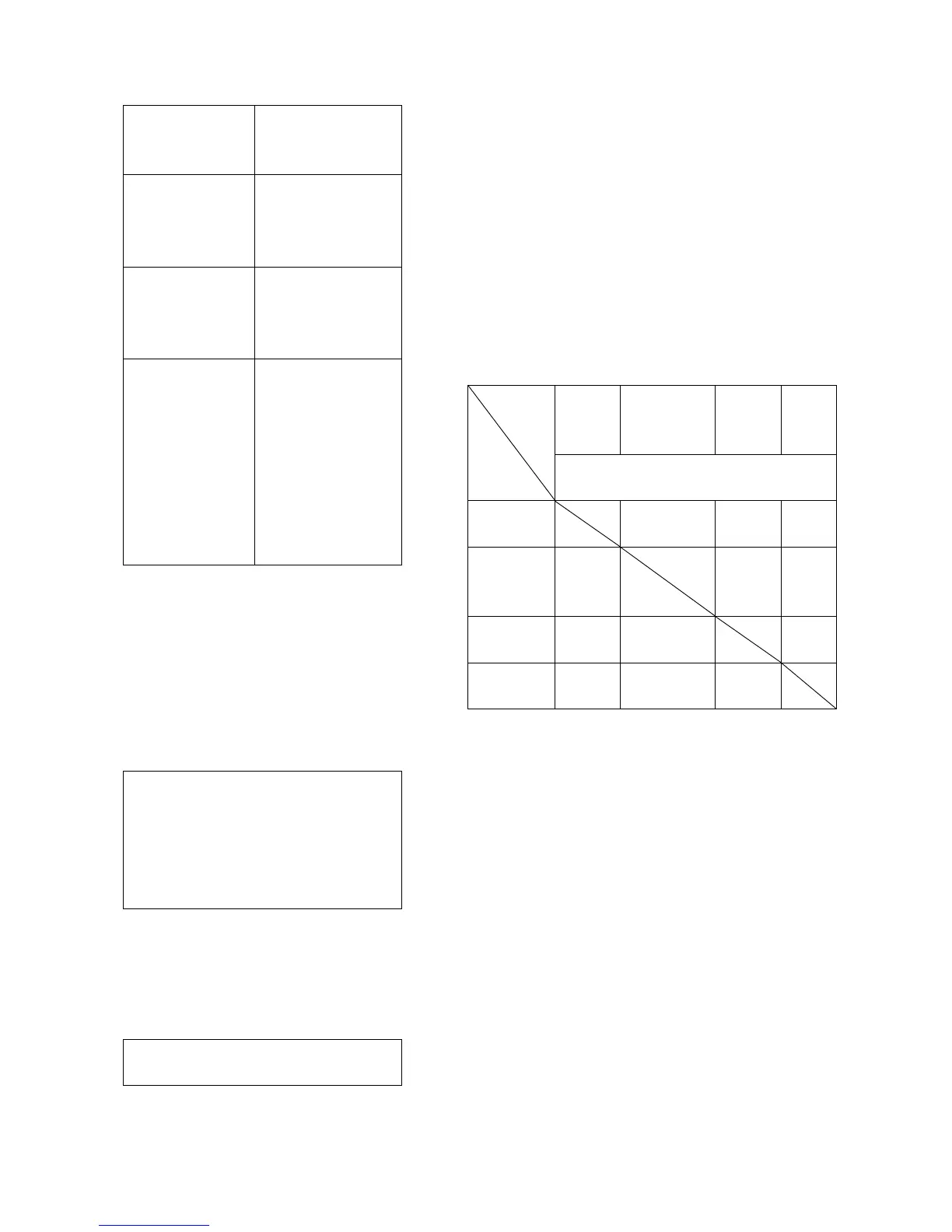
Multimeter
P
N
Unit:MΩ
White(A)
0 6.5 19~21
Green/Red
(L)
1~10 24~25 19~23
Red(B)
10~50 0 19~21
Black(E)
5~15 0 0