53
3rd Wave User Manual
Filters
Filters
The Filters
If you recall, the oscillators produce the raw sound of the synthesizer.
The lters do exactly what their name suggests: they take in this raw
sound and lter something out — in this case, harmonic frequencies.
This gives you the power to change the character of the raw sound.
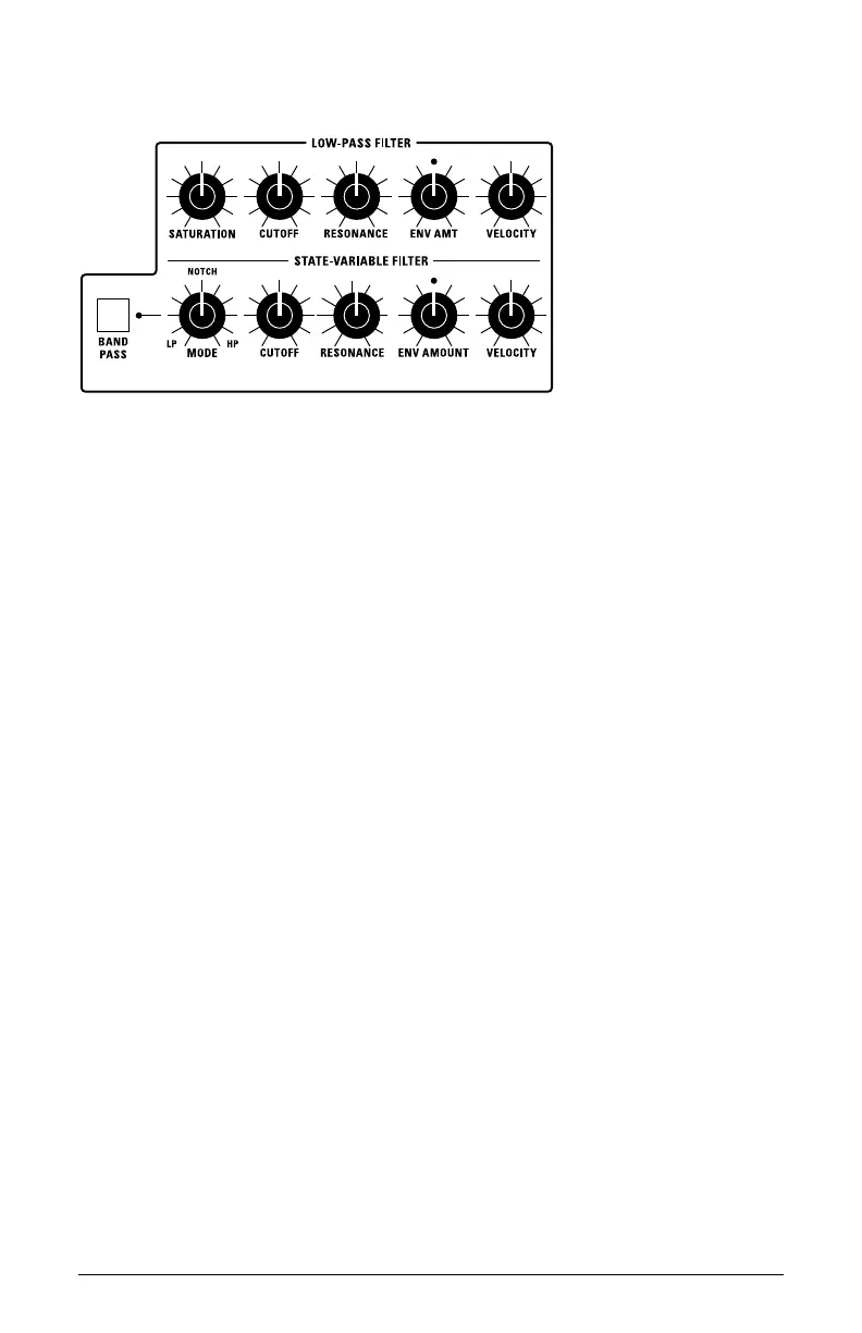
The 3rd Wave has two separate lters: a 4-pole analog low-pass lter and
a zero-delay, 2-pole digital state-variable lter.
Here’s how they each work:
• LOW-PASS FILTER: This is a classic, 4-pole, 24db per-octave reso-
nant lter that cuts out high frequencies and passes low frequencies.
• STATE-VARIABLE FILTER: This is a zero-delay, 2-pole, 12db per-
octave resonant lter that can be continuously varied between low-
pass, notch, and high-pass operation. It has a dedicated switch that
enables Band-Pass mode. Each mode does what its name suggests. The
State-Variable lter cannot self-oscillate. Another characteristic of the
State-Variable lter is that increasing the amount of resonance does not
decrease the amount of low-frequencies (bass).
The best way to get a feel for what the lters do and how they sound is to
give their Cutoff knob a good twist, with and without a bit of Resonance.
The two lters operate in series — the State-Variable Filter rst,
followed by the Low-Pass Filter. Using the two together, with different
cutoff, resonance, and for the state-variable lter
mode settings creates a
wide tonal variety. Try using the Mod Matrix to route a second envelope
— Envelope 3 or 4 — to the state variable lter in addition to the stan-
dard Filter Envelope for some interesting effects.