English (GB)
11
6.3 Pump variant
The IO 111 must be set to the actual pump. In the
pump type designation there is an A, B, or C.
Example 1, internal wiring:
SE1 80 80 40 A Ex 4 5 1D
Example 2, external wiring:
SE2.90.250.2250.4.S.496.Ex.S.5.13.C.Q.S
These letters (A and C in the examples) can be
found on the pump nameplate and refer to the
setting of DIP switches 1 and 2.
See wiring diagrams at the end of this booklet or the SM 111 installation and operating instructions.
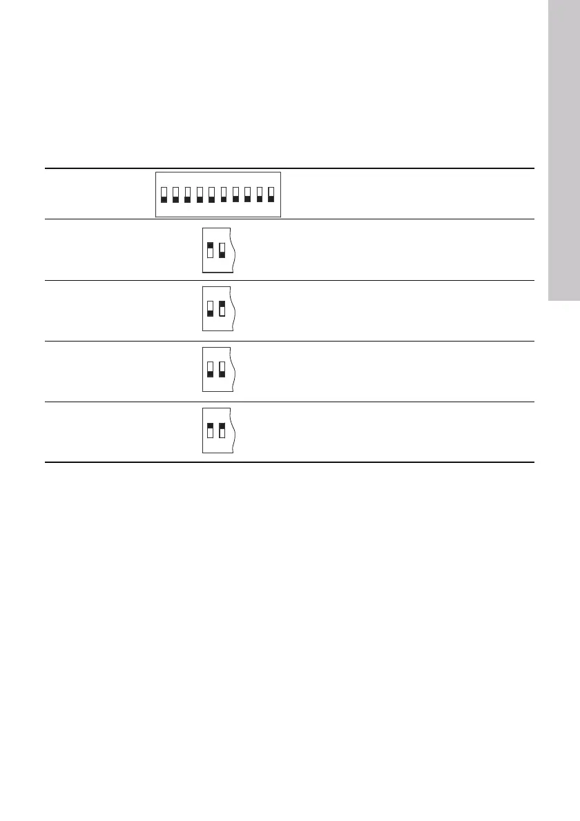
Pump variant Description
Variant A
Installation without SM 111.
Sensors are connected directly to the IO 111.
Variant B
Installation with SM 111.
PTC sensors are not connected to the SM 111, but
must be hardwired out of the pump.
Variant C
Installation with SM 111.
PTC sensors in the stator windings are connected to
the SM 111.
Variant D
Installation without SM 111.
All sensors are hardwired out of the pump.
The IO 111 can be used for indication of water in oil
and as PTC relay.
ON
12
ON
12
ON
12
ON
12
Grundfos.bk Page 11 Tuesday, January 25, 2011 12:56 PM

 Loading...


