English (GB)
20
3
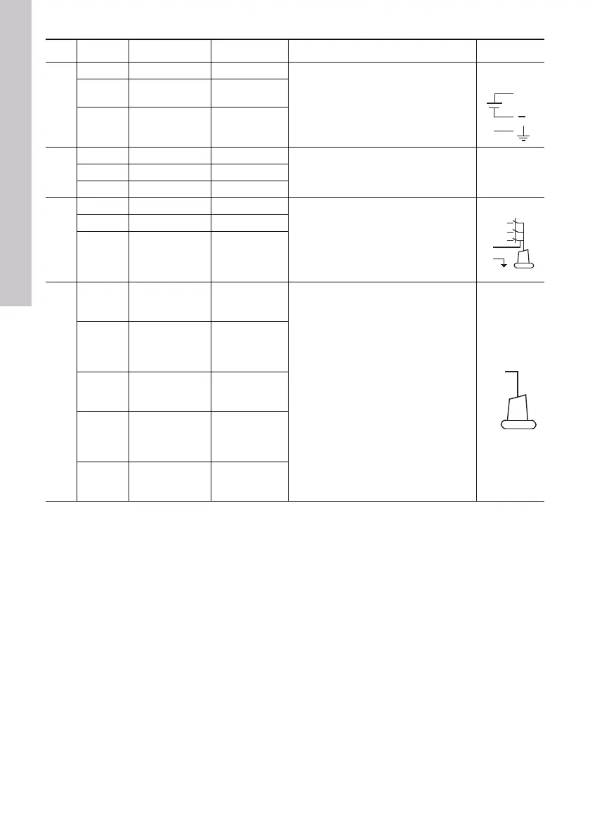
PE Earth Earth
Supply voltage to the IO 111
-
GND for supply
voltage
0 VDC
24 VAC ± 10 %
+
Plus for supply
voltage
24 VAC ± 10 %
24 VDC ± 10 %
5
A RS485 A Bus input
RS485 communication connection
(9600 baud)
Y RS485 GND 0 V
B RS485 B Bus input
9
I1 Earth Earth
The insulation resistance between
stator windings and earth is measured.
The measurement is only correct when
the motor is stopped.
Measurement voltage: 10 VDC.
I2 Not connected -
I3
Terminal for
measurement of
stator insulation
resistance
CAT II 600 V
10
P1
Terminal for
sensors in the
pump
Sensor input
Thermal switch or PTC sensor
according to DIN 44081 and 44082.
P1 to P5 are used for the connection of
sensors in the pump. All sensors in
contact with phase voltage must be
double insulated according to
EN 61010-1.
P2
Terminal for
supply voltage
to sensors in
the pump
15 V
P3
Terminal for
sensors in the
pump
Sensor input
P4
Terminal for
supply voltage
to sensors in
the pump
15 V
P5
Terminal for
sensors in the
pump
Sensor input
Pos. Terminal Description Data Function Diagram
+
Grundfos.bk Page 20 Tuesday, January 25, 2011 12:56 PM

 Loading...


