100 ACO6800+ Installation and Operation Manual
Copyright © 2009, Harris Corporation
Chapter 8: ACO6800+ISCST Parameters, LEDs, and Alarms
Monitoring LEDs
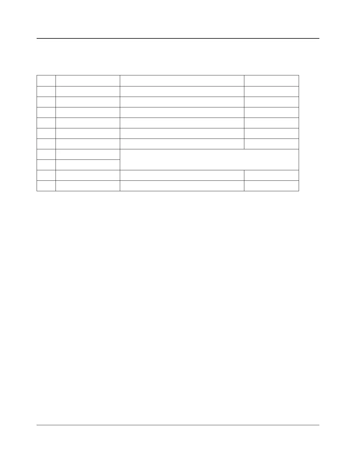
Table 8-5. ACO6800+ISCST Monitoring LEDs Indicators
LED Name Description Color Indication
1 Out A LED 1 The current selected input is IN 1. Green
2 Out A LED 2 The current selected input is IN 2. Green
3 IN 1A Present Input 1 signal is present. Green
4 IN 1A Alarm Input 1 is in an alarm state. Amber
5 IN 2A Present Input 2 signal is present. Green
6 IN 2A Alarm Input 2 is in an alarm state. Amber
7 Out B LED 1
Not used
8 Out B LED 2
9 Genlock Present Genlock is present. Green
10 Genlock Alarm Genlock is in an alarm state. Amber