96 ACO6800+ Installation and Operation Manual
Copyright © 2009, Harris Corporation
Chapter 8: ACO6800+ISCST Parameters, LEDs, and Alarms
ACO6800+ISCST Subdevice Parameters
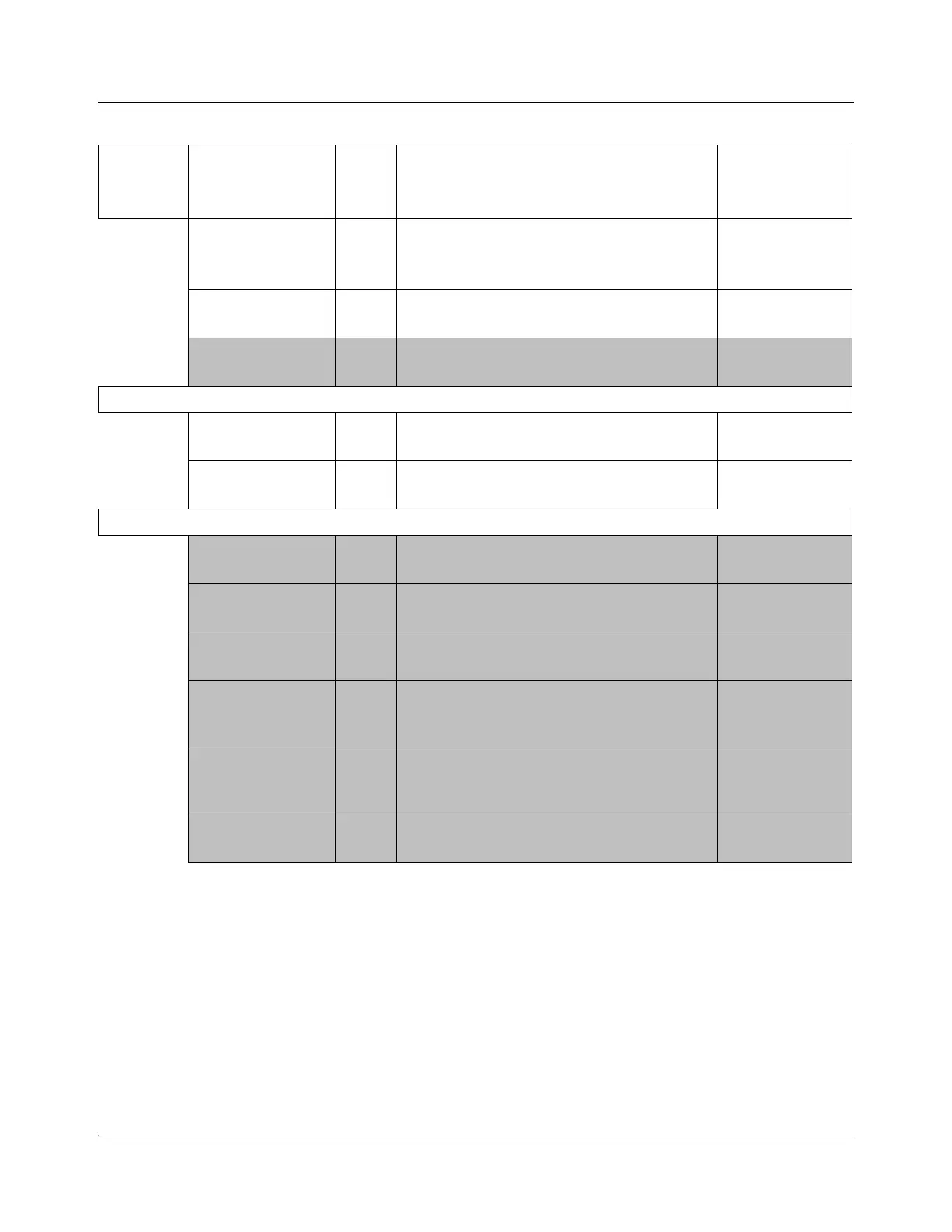
The parameters in SDI mode and in ASI mode cannot be shown at the same
time.
AUX Source 1, F Sets the backup channel’s output source
• AUX
•IN_1
•IN_2
Relay Bypass 1, 1 Determines whether or not the relay bypass is
activated
•On
• Off
Relay Status [RO] Displays whether or not the bypass relay has been
activated
•On
•Off
System > General Purpose Interface
GPI Input Trigger
Level
1, 2 Sets the trigger level for GPI Input of Group A
• Low Level
• High Level
GPI Output Trigger
Level
1, 3 Sets the trigger level for GPI Output Group A
• Low Level
• High Level
System > General Purpose Interface (Continued)
GPI Input_1 [RO] Displays whether or not GPI Input_1 has been
switched to A1
•N/A
• Switch to IN_1
GPI Input_2 [RO] Displays whether or not GPI Input_2 has been
switched to A2
•N/A
• Switch to IN_2
GPI Input_3 [RO] Displays whether or not GPI Input_3 has been
switched to Relay Bypass
•N/A
• Relay Bypass
GPI Output_1 [RO] Displays whether or not output A1 is online
•N/A
• Input IN_1
online
GPI Output_2 [RO] Displays whether or not output A2 is online
•N/A
• Input IN_2
online
GPI Output_3 [RO] Displays whether or not the relay bypass has been
activated
•N/A
• Signal Bypass
Table 8-3. ACO6800+ISCST ASI Parameters (Continued)
Group Parameter Name
Bank,
Switch
Function Options