ACO6800+ Installation and Operation Manual 7
Copyright © 2009, Harris Corporation
Chapter 1: Introduction
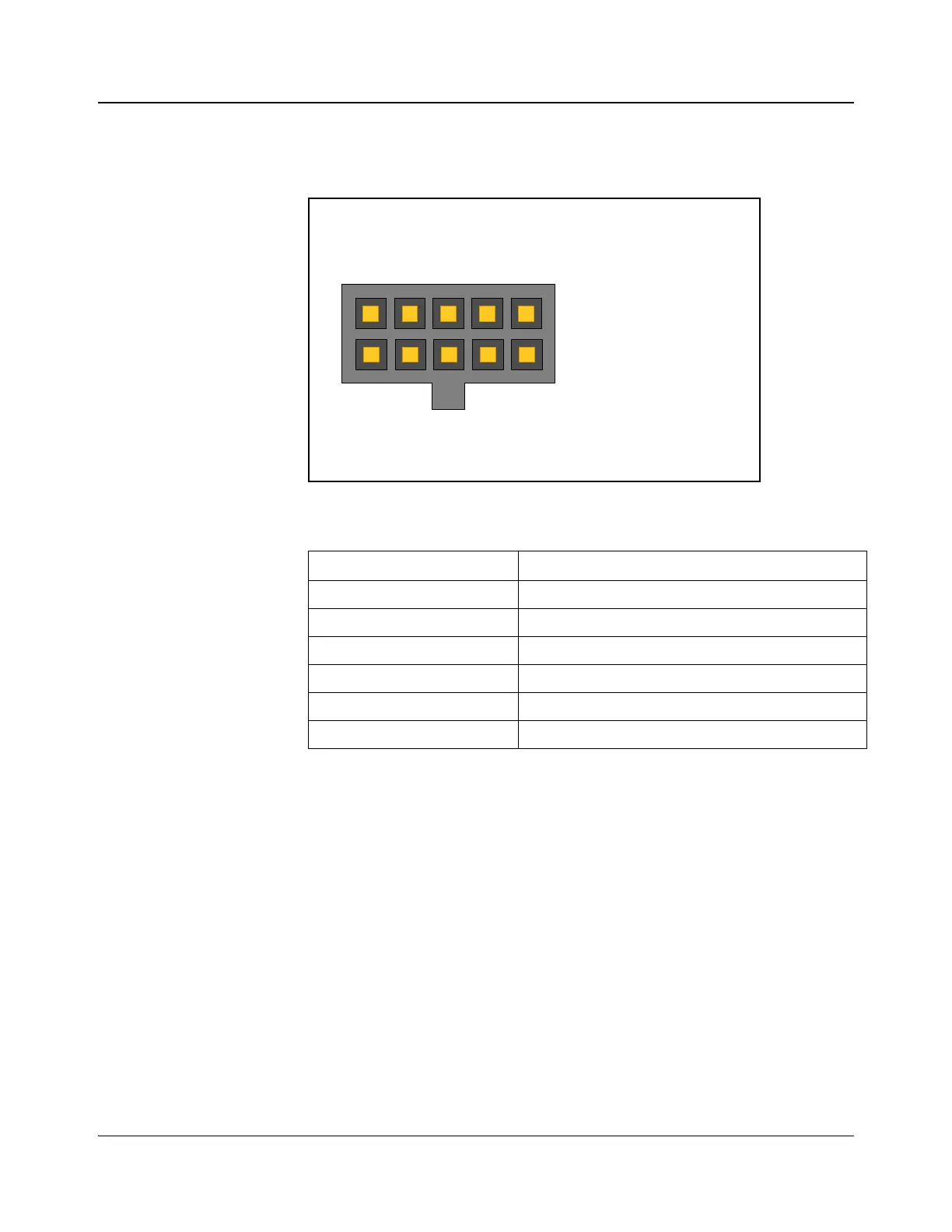
GPI Mating Connector
The GPI Connector cable (provided) has the following connections:
Figure 1-3. GPI Connector Pinouts
Table 1-3. GPI Functions
GPI Function
GPI In 1 Switch to IN 1
GPI In 2 Switch to IN 2
GPI In 3 Force relay to bypass signal IN 1
GPI Out 1 Indicate IN 1 is selected as output source
GPI Out 2 Indicate IN 2 is selected as output source
GPI Out 3 Indicate signal IN 1 is bypassed
1. GPI In 1
2. Ground
3. GPI In 2
4. Ground
5. GPI In 3
6. GPI Out 1
7. Ground
8. GPI Out 2
9. Ground
10. GPI Out 3