Harris Corporation Constellation™
Wiring Specifications A-7
WIRING
SPECIFICATIONS
Alarm I/O Pinouts
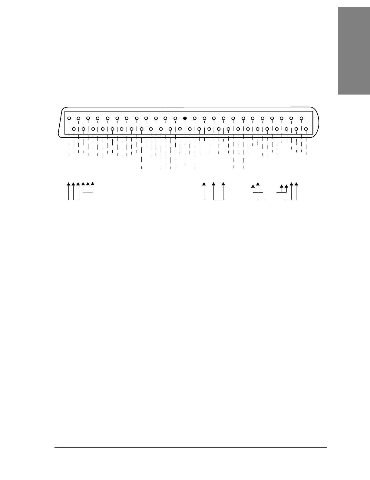
Figure A-8 shows the Alarm I/O pinouts.
Figure A-8:
Access Area for Interconnection Cabling
Located at the bottom right-hand side of the card cage, connectors are available
for customer interconnection cables. Refer to Figure A-9
and Table A-3.
1
26
27
28
3
29
4
30
5
31
6
32
7
33
8
34
9
35
10
36
11
37
12
38
13
39
14
40
15
17
16
18
41
44
42
43
19
20
45
46
48
47
21
22
23
24
49
50
25
2
Fuse Alarm
Callout
Relay
Fan Alarm
Major
Alarm
(default)
Minor
Alarm
(default)
RELAY 1 NC
RELAY 1 NO
RELAY 1 COM
RELAY 2 COM
RELAY 2 NC
RELAY 2 NO
RELAY 4 NC
RELAY 4 NO
RELAY 4 COM
RELAY 3 COM
RELAY 3 NC
RELAY 3 NO
RELAY 5 NC
RELAY 5 NO
RELAY 5 COM
NC
RELAY 7 COM
RELAY 7 NO
RELAY 7 NC
NC
NC
NC
NC
EXT ALARM 1
GND
EXT ALARM 2
NC
EXT ALARM 3
FAN ALM RELAY NO
EXT ALARM 4
FAN ALM RELAY COM
EXT ALARM 5
FAN ALM RELAY NC
EXT ALARM 6
NC
EXT ALARM 7
NC
EXT ALARM 8
CALLOUT RLY NC
FA RELAY NC
RELAY 6 NC
RELAY 8 NC
RELAY 6 COM
RELAY 6 NO
CALLOUT RLY COM
CALLOUT RLY NO
FA RELAY COM
FA RELAY NO
RELAY 8 COM
RELAY 8 NO
 Loading...


