Harris Corporation Constellation™
Installation and Commissioning 4-13
INSTALLATION AND
COMMISSIONING
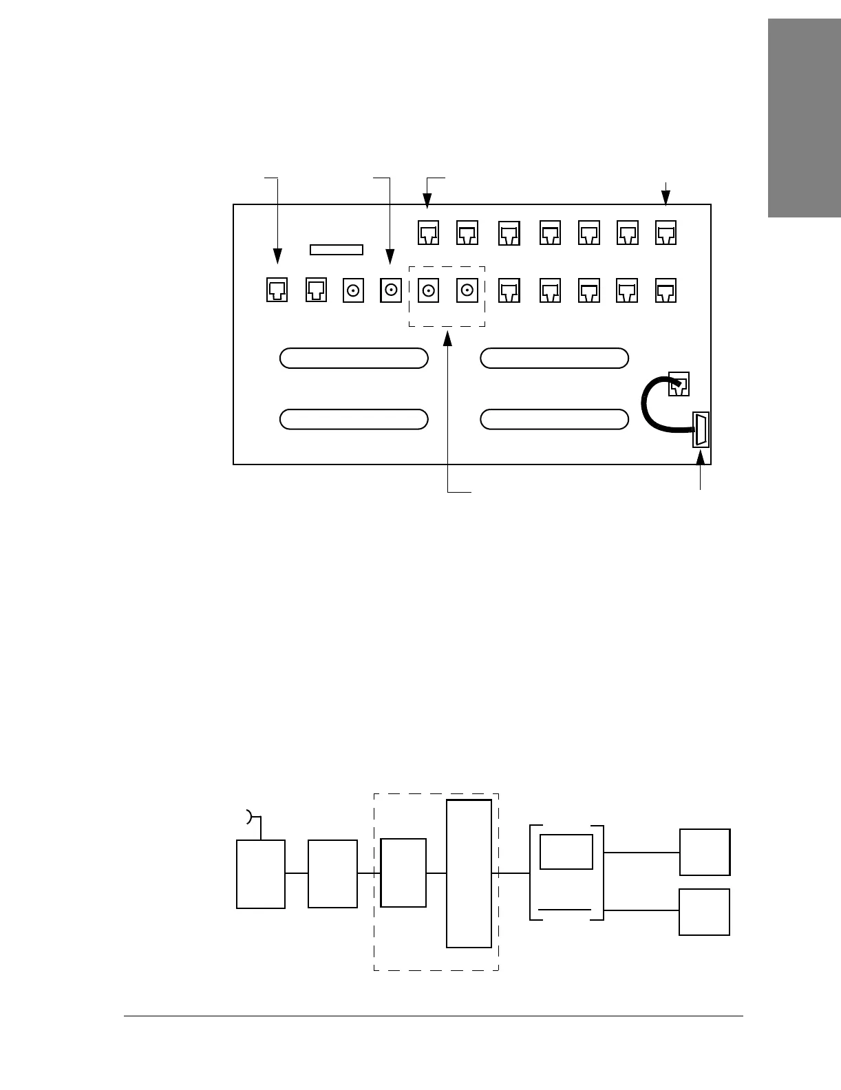
Figure 4-5: Customer access area
a. You may need to remove the Fan Assembly for easier installation of the
cables. See page 12-5
for instructions on how to remove the Fan
Assembly.
b. Install the cables through the right port hole of the card cage.
If the Fan Assembly was removed, reinstall the Fan Assembly. See page 12-7 for
instructions on how to install the Fan Assembly.
Figure 4-6: Interconnection cabling, DS1 configuration
Wayside
Monitor
VersaT1lity
VF Port 1
VF Port 2
Wayside
Out
Wayside
In
Data
Port 2
DS3 Out
DS3 In
Handset 2Handset 1
Aux
Ethernet
Spur
Keypad
Can
Fan
DS1 17-32 Out
DS1 1-16 In
DS1 17-32 In
DS1 1-16 Out
FSCAN
DE-9
RJ-45
T1 Wayside1
E1 Wayside, SDH option only
RJ-11
26
25
26
25
25
25
26
26
1
1
1
1
50
50
50
50
BNC
Data
Port 1
Notes:
1. The wayside connection for T1 is not for 1xDS3 but only for OC-3, 3xDS3,
and 2xDS3 +28xDS1.
2. DS1 In = Input to the radio from the customer’s DSX.
3. DS1 Out = Output from the radio to the customer’s DSX.
J1
J3
J1 J1
J3
J2
J2
J3
J2
J3
J3
J2
J2 J2
J2
J2
J1
J1
J2
J2
J3
P15
P14
Radio
Modem
HLM
M12
Units
DS1
or
DS1
Jackfield
DS1
Cross-
Connect
Digital
Channel
Bank
Application 1
Application 2
Mux