Constellation™ 2002 June 20
4-22
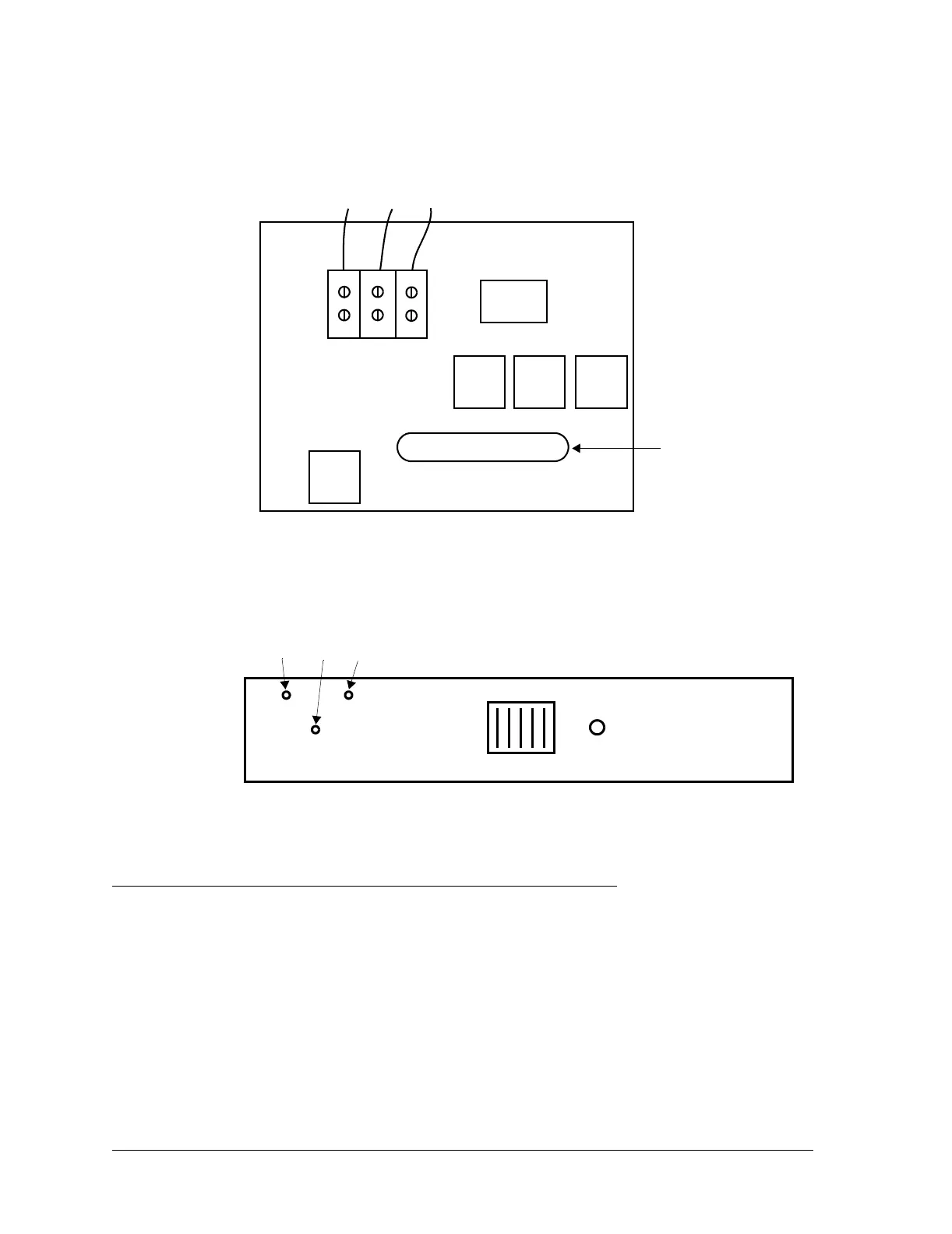
Figure 4-14: Constellation backplane, terminal
Repeater.
Connect the wires to the quick disconnect tabs behind the Fuse Panel (Figure
4-15).
Figure 4-15: Fuse Panel, repeater
Detailed Turn-on Procedures
1. Ensure that the correct fuses are installed
.
BAT A
BAT B
RET
24/48VDC
HARRIS Constellation Backplane
TO FUSE PANEL
ALARM I/O
Filter
Filter
Filter Filter
26
1
25
50
Red
White
Black
J1
J2
External
alarm/control
connector
DC IN B
(P3)
DC IN A
(P6)
RETURN
(P2)
Red
White
Black
FUSE
ALARM