Harris Corporation Constellation™
Configuring the Constellation Radio 6-3
CONFIGURING THE
CONSTELLATION
RADIO
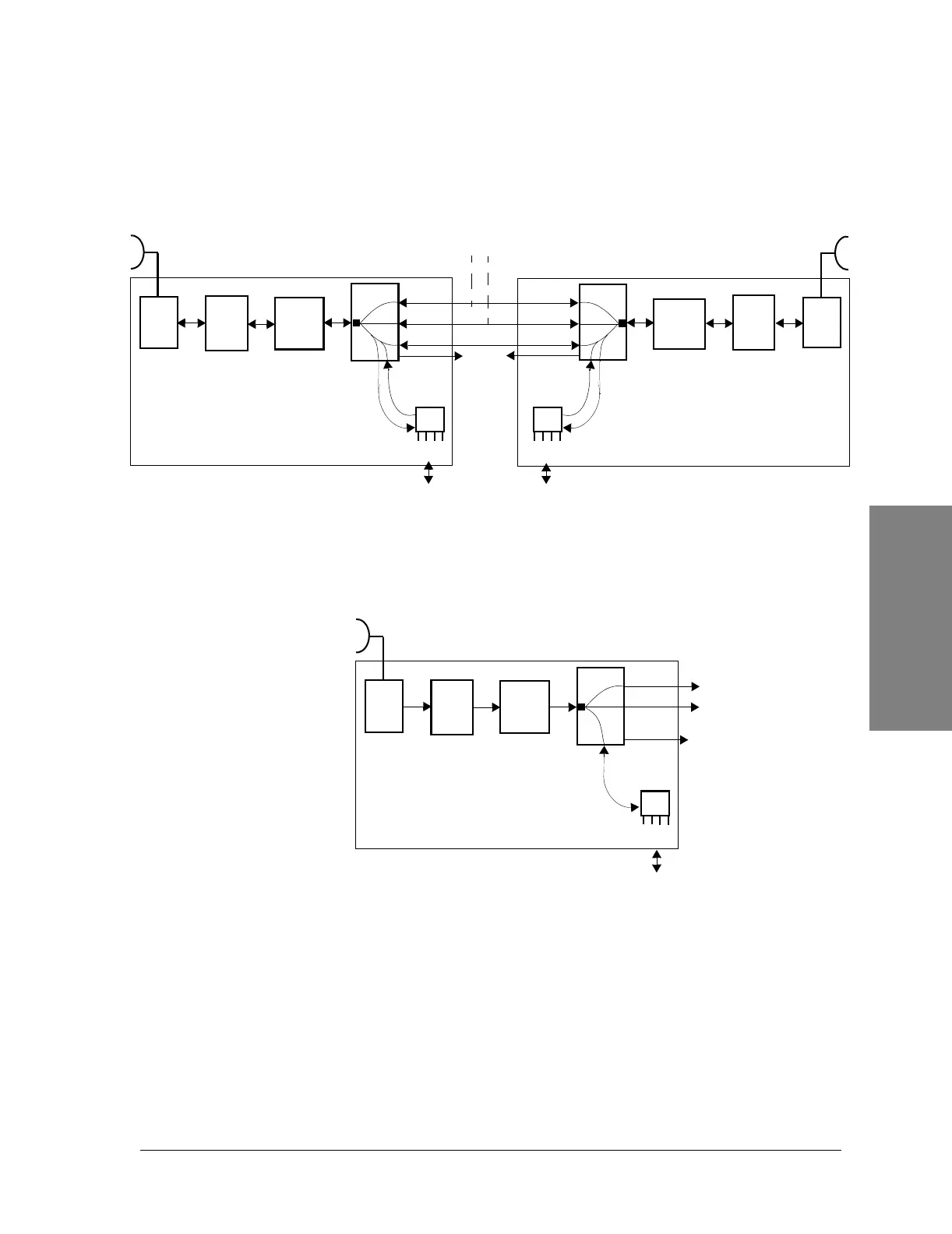
Figure 6-2: Example of DS3 channel with partial add/drop,
back-to-back terminals
Figure 6-3: Example of a DS3 channel dropping 28 T1
USED CAPACITY and PROTECTION
Each M12 Unit can transmit and receive four DS1 signals. Select the number of
tributaries you are using. See Table 6-2.
n
DS3-1
DS3-2
DS3-3
RF
shelf
HLM
Modem
ACU
RF
shelf
HLM
Modem
ACU
T1 signals
n x T2
Customer
(Add/Drop)
n
M12 Unit(s)
T1 signals
n x T2
Customer
(Add/Drop)
DS3-1
DS3-2
DS3-3
DS3
Customer interface
NOTES
n = Number of M12 Units (1 to 4)
T2 = 4 DS1 = 1 M12
T3 = 7 T2 = 28 T1
M12 Unit(s)
Wayside
DS1
DS1
1-7
DS3-1
DS3-2
RF
shelf
HLM
Modem
ACU
28 DS1s
Customer
M12 Units
Wayside
DS1
 Loading...


