Harris Corporation Constellation™
Installation and Commissioning 4-33
INSTALLATION AND
COMMISSIONING
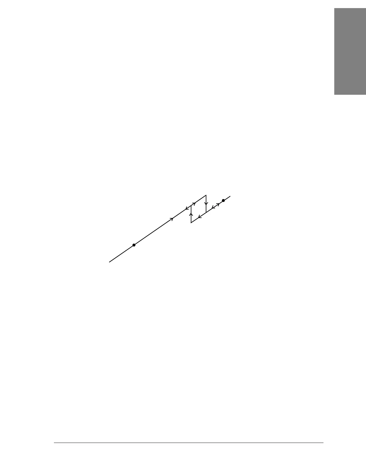
The voltage reading is negative and approaches zero as the RSL
increases.
For example:
At -50 dBm, the meter reading is -5.0 Vdc.
At -40 dBm, the meter reading is -4.0 Vdc.
See also Figure 4-19.
RSL Test Point.
At nominally -26 dBm or higher, a 10 dB attenuator is engaged, resulting in a 1
volt drop (apparent 10 dB) in the RSL test point reading. The Keypad will
display the corrected (unattenuated) value. At nominally -29 dBm, the
attenuator is disengaged, and the meter will reflect the unattenuated value. See
Figure 4-19.
Figure 4-19: RSL measurement
If the signal level is too high for antenna alignment, the far-end Transmitter
could be set to ATPC low power (about 10 dB lower than nominal high power
setting). See Keypad menu, Appendix B.
CONFIGURATION > SYSTEM > TX ATPC > DISABLE LOW
If the signal level is still too high, a pad can be temporarily added at the
Receiver input.
-26 dBm (-2.6 Vdc*)
-70 dBm
(-7.0 Vdc)
-20 dBm (-3.0 Vdc)
-29 dBm
(-3.9 Vdc***)
(-3.6 Vdc**)
(-2.9 Vdc
#
)
LEGEND
( ) Test point reading.
* Before the attenuator is engaged.
** After the attenuator is engaged.
*** Before the attenuator is disengaged.
#
After the attenuator is disengaged.