Harris Corporation Constellation™
Installation and Commissioning 4-29
INSTALLATION AND
COMMISSIONING
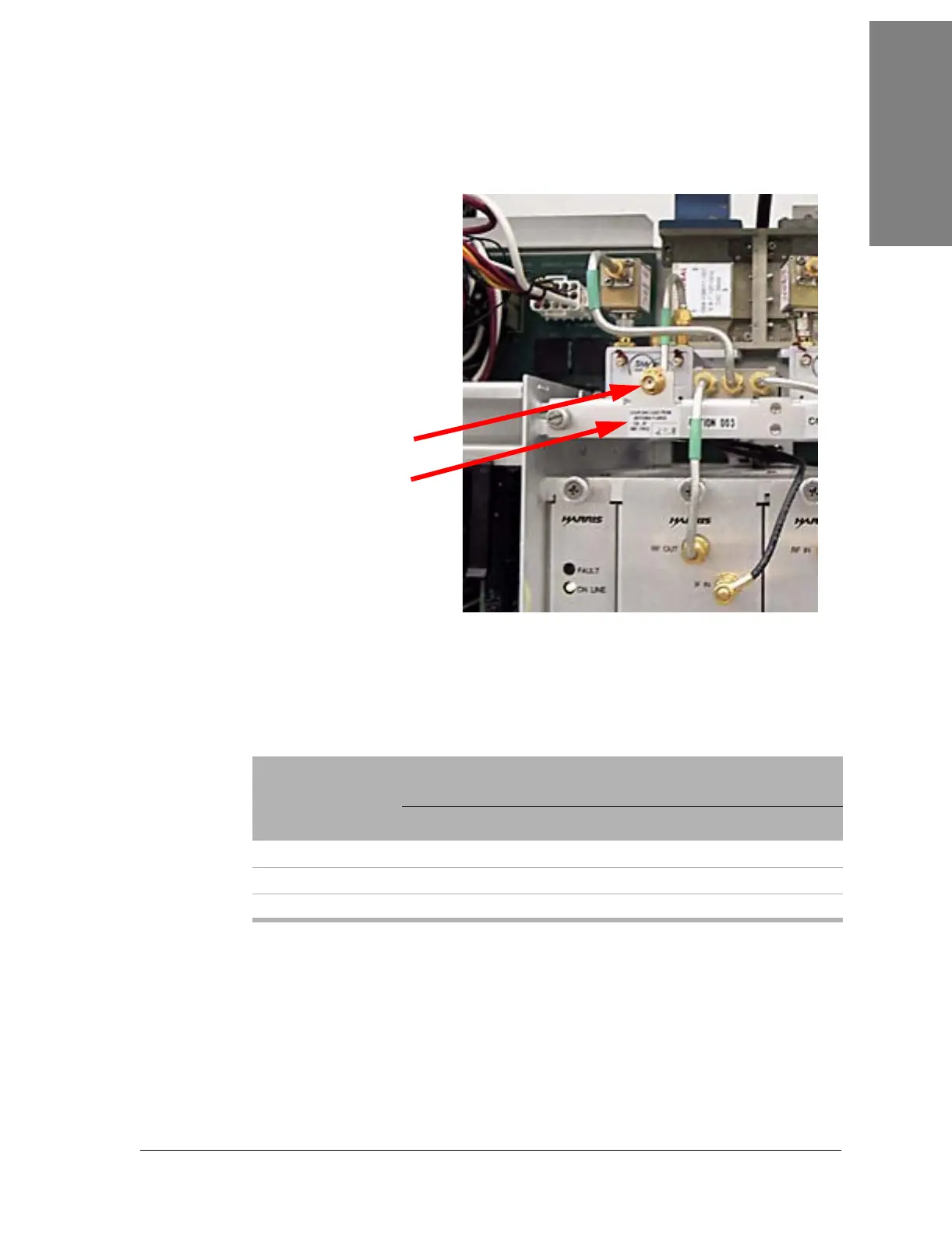
Figure 4-18: Location of the transmit monitor port
Power Meter Reading.
c. The Power Meter reading should equal the value from
Table 4-14 or Table 4-15 minus the Coupling Loss on the label.
Table 4-14: Power at antenna flange, NP configuration
TX Frequency
(GHz)
8T 16T 28T/DS3 OC3/3xDS
3
Power (dBm)
6 29.5 28.5 29.0 29.0
7/8 27.5 26.5 27.0 27.5
10/11 26.0 24.5 25.0 25.0
Label:
COUPLING LOSS FROM
ANTENNA FLANGE
CAL AT
XMT FREQ
Transmit monitor port
 Loading...


