10.1 Connecting the External Input/Output Terminal
151
1
2
3
4
5
6
7
8
9
10
11
The external input/output terminal uses 0/5-V logic signals or short/
open contact signals to control the 3169-20/21. For connection, the
optional 9440 cable is required.
Using the External Input/Output
Terminal
10
10.1 Connecting the External Input/Output
Terminal
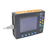
Insert the 9440 connection cable into the
external input/output terminal (EXIT I/O),
aligning the connector guide grooves (the
connector is equipped with a lock). When
removing the connection cable, hold it by
the plastic part.
Pin No. Signal Name 9440 Cable Color
1 Start/stop (input) Red
2-- White
3 Status (output) Black
4 Data storage (input) Yellow
5 Ground (common) Blue
Connecting the External Input/Output Terminal
9440 CONNECTION CABLE
External input/output
connector (EXT I/O)
A plastic connector is used for the connection cable. Do not
insert it into the terminal without aligning the guide grooves or
pull it without releasing the lock, to prevent damage to the con-
nector.

 Loading...