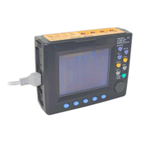
3.3 Connecting the Voltage Cords
27
1
2
3
4
5
6
7
8
9
10
3.3 Connecting the Voltage Cords
Connect the voltage cords to the product first, and then to
the active lines to be measured. Observe the following to
avoid electric shock and short circuits.
• Voltage cable should only be connected to the secondary
side of a breaker, so the breaker can prevent an accident if
a short circuit occurs. Connections should never be made
to the primary side of a breaker, because unrestricted cur-
rent flow could cause a serious accident if a short circuit
occurs.
• Do not allow the voltage cable clips to touch two wires at
the same time. Never touch the edge of the metal clips.
• Voltage input terminals U
1
, U
2
, and U
3
are common to the N
terminal and are not insulated. To avoid the risk of electric
shock, do not touch the terminals.
• For safety reasons, when taking measurements, only use the
9438-03 VOLTAGE CORD provided with the product.
• The supplied voltage cords consist of one each red, yellow, blue
and black cords. Connect only the cords actually needed for
measurement. Cords not being used for measurement should
be disconnected.
Be sure to hold the voltage cable by its plug when connecting or dis-
connecting the cable.
Insert plugs all the
way in.
1.
Connect the voltage cables
to the voltage input termi-
nals of the 3169-20/21. The
number of voltage cables
required depends on the
line to be measured.
2.
Fully insert the cable plug.
Connecting the voltage cords to the instrument

 Loading...