9
_____________________________________________________________________________________________
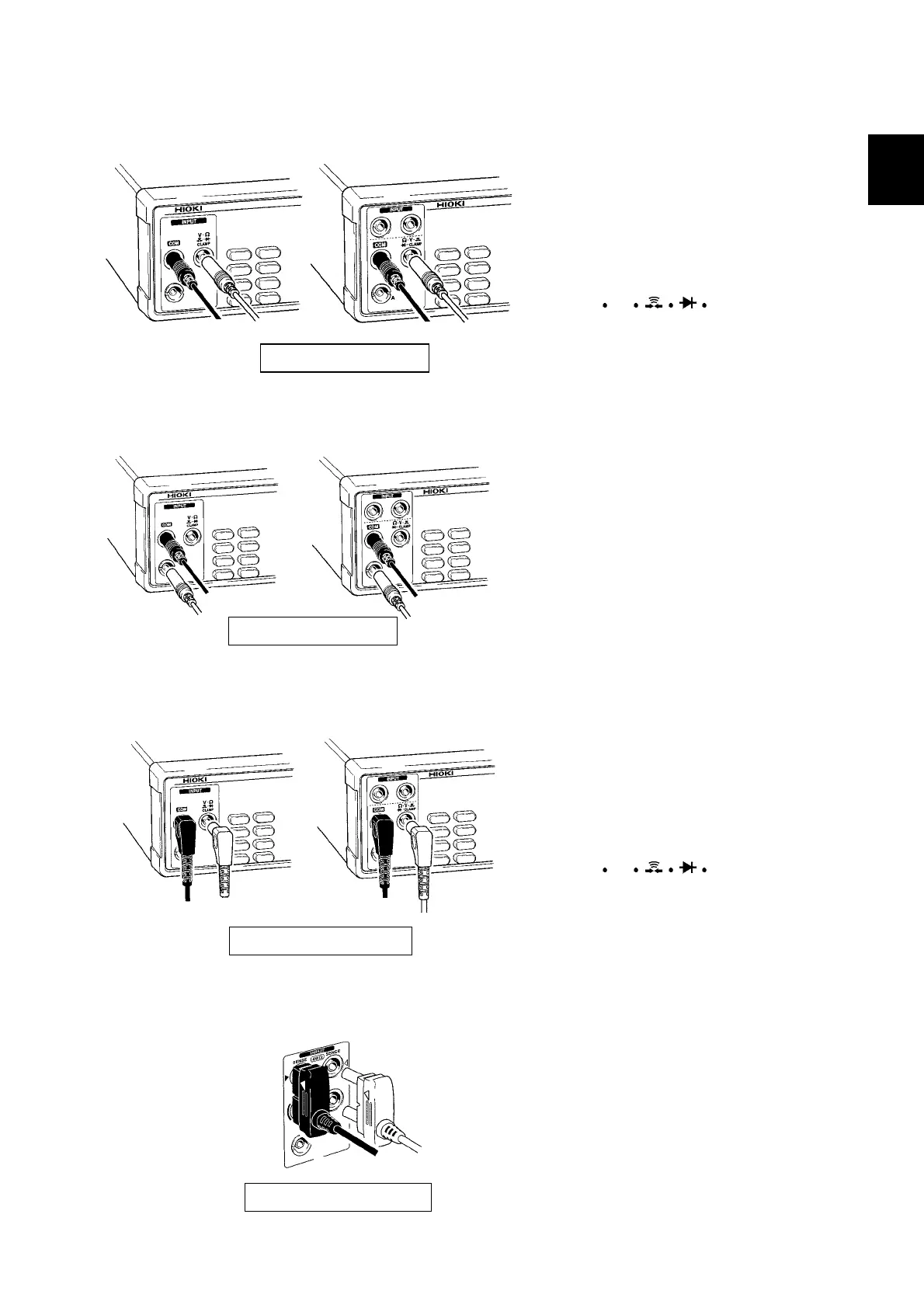
2.2 Test Lead/Clamp Sensor Connection
______________________________________________________________________________________________
1
2
3
4
5
6
7
8
9
10
11
12
13
14
A
Red
Black
Red
Black
32393237/38
L9170-10 TEST LEAD
Red
Black
3239
3238
Red
Black
L9170-10 TEST LEAD
Red
Black
Red
Black
3239
3237/38
Clamp sensor connector
Red
3239
Black
L2107 CLIP TYPE LEAD
(1) Voltage measurement/ 2-terminal resistance measurement/
continuity test/ diode test/ frequency measurement
1
. Disconnect the L9170-10 TEST LEAD
from the sample being measured.
2
. Connect the black lead to the COM
terminal and the red lead to
the V Ω CLAMP terminal.
(2) Current measurement
1
. Disconnect the L9170-10 TEST LEAD
from the sample being measured.
2
. Connect the black lead to the COM
terminal and the red lead to the A-
terminal.
(3) Clamp current measurement
1
. Disconnect the clamp sensor from the
sample being measured.
2
. Connect the black lead to the COM
terminal and the red lead to
the V Ω CLAMP terminal.
(4) 4-terminal resistance measurement
1
. Disconnect the clamp sensor from the
sample being measured.
2
. Connect 4-terminal test leads like
those of the L2107 as shown in the
drawing. Align the triangular mark on
the red lead with the red triangular
mark on the chassis, and the triangular
mark on the black lead with the black
triangular mark on the chassis.