15
_____________________________________________________________________________________________
3.3 4-Terminal Resistance Measurement
______________________________________________________________________________________________
1
2
3
4
5
6
7
8
9
10
11
12
13
14
A
DANGER
Never apply voltage to test leads and SENSE terminal when the
Resistance, Low-power resistance or Continuity Check are selected.
Doing so may damage the product and result in personal injury.
To avoid electrical accidents, remove power from the circuit before
measuring.
Red
Black
3239
L2107 CLIP TYPE LEAD
NOTE
When measuring high resistance, there are cases in which an overload (
“
OF
”
displayed) occurs owing to external noise. Do not use the unit near fluorescent light
or power line.
When external noise is high, please shield the red lead (connected to the V
Ω
CLAMP terminal) and the sample to be measured. Connect the outer shield cover to the
COM terminal. (Or use a shielded line, such as the 9326 CONNECTION CORD.) In case
of using a dial resistor, connect the GUARD terminal to the COM terminal of the unit.
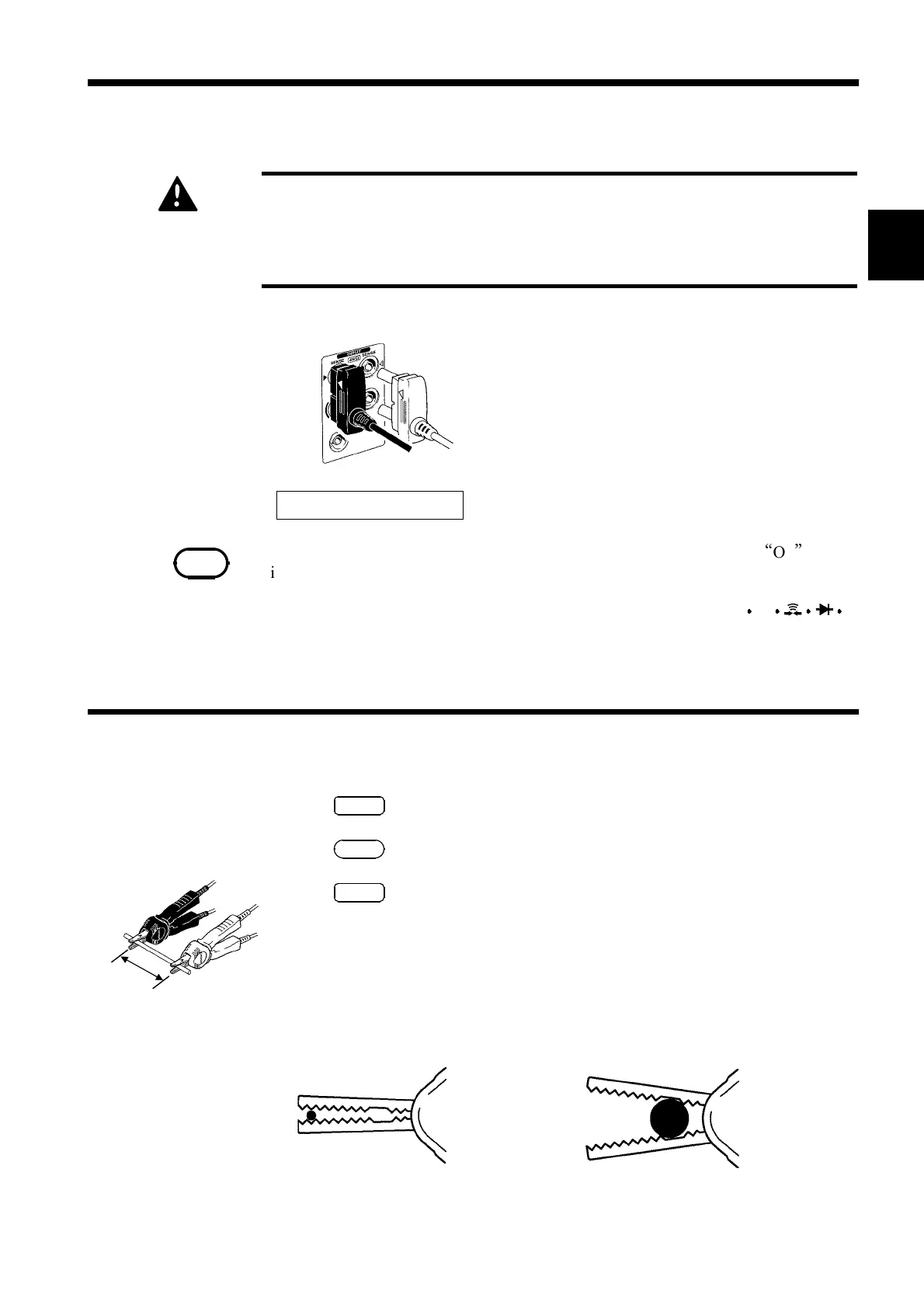
3.3.1 Resistance Measurement (4-Terminal, on 3239 only)
Rx
When clipping a thin line
Cli
the line at the ti
,
When clipping a thick line
Cli
the line at the dee
non-
3.3 4-Terminal Resistance Measurement
The four terminals of the L2107 CLIP TYPE
LEAD
Verify that all four terminals (SOURCE+,
SOURCE-, SENSE+, and SENSE-) are
connected. Also verify that the triangular mark
on the red lead is aligned with the red
triangular mark on the chassis, and that the
triangular mark on the black lead is aligned
with the black triangular mark on the chassis.
1
.Press
SHIFT
."SHIFT" lights up on the display.
2
.Press
Ω
."4W" lights up on the display.
3
.Press
SMPL
to select a sampling period.
(See 4.2 Switching of Sampling Period.)
4
. Performs zero-ajust for the 3237/38/39.
(See 4.3 Zero Ajust Function.)
5
. Connect the test lead to the sample being measured and read the value.