44
_____________________________________________________________________________________________
6.1 Explanation of Signal Wires
______________________________________________________________________________________________
CAUTION
To prevent damage to this unit, please observe the following precautions:
Do not apply a voltage or current exceeding the rated values to the external
output terminal or external control terminal.
When using a relay, always attach a flyback diode.
Take care not to short-circuit the external output terminal and the external
control terminal.
Take care not to short-circuit INT.DCV and INT.GND.
When a device is to be coupled to the external output terminal or external
control terminal, be sure to connect the device to ground. Failure to do so
may destroy measurement system insulation.
To prevent electric shock, please observe the following precautions:
When a device is to be connected to this unit, switch it off before coupling
it to the terminal. Establish cable connections securely to prevent
dislocation during operations and subsequent contact with conductive parts
of the unit casing or test leads.
INT.GND is connected to ground. If a controller has a potential to ground,
a short-circuit will occur.
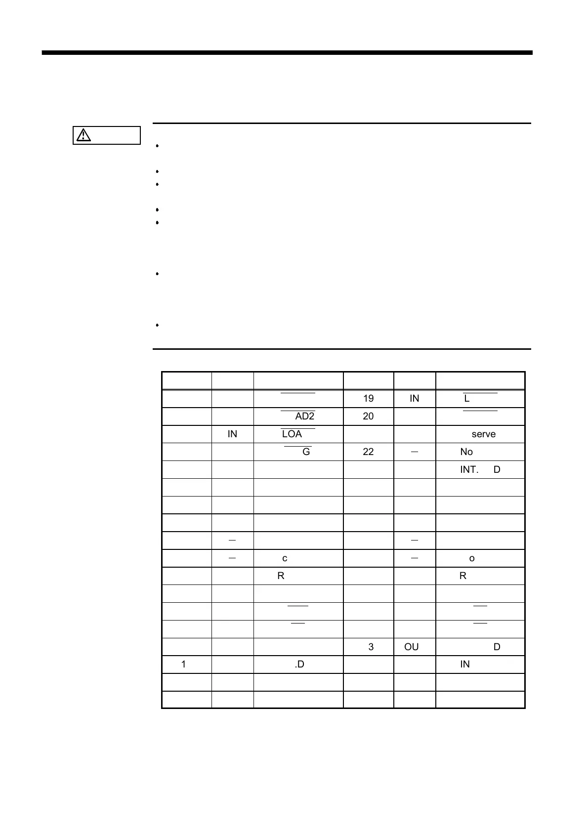
Pin No. I/O Signal line name Pin No. I/O Signal line name
1 IN LOAD0
―――――
19 IN LOAD1
―――――
2 IN LOAD2
―――――
20 IN LOAD3
―――――
3 IN LOAD4
―――――
21 IN (Reserved)
4 IN TRIG
――――
22
-
Not used
5 OUT INT.DCV 23 OUT INT.GND
6 OUT INT.DCV 24 OUT INT.GND
7 OUT INT.DCV 25 OUT INT.GND
8 OUT INT.DCV 26 OUT INT.GND
9
-
No connection 27
-
No connection
10
-
No connection 28
-
No connection
11 OUT (Reserved) 29 OUT (Reserved)
12 OUT (Reserved) 30 OUT (Reserved)
13 OUT EOC
―――
31 OUT Hi
――
14 OUT IN
――
32 OUT Lo
――
15 OUT INT.DCV 33 OUT INT.GND
16 OUT INT.DCV 34 OUT INT.GND
17 OUT INT.DCV 35 OUT INT.GND
18 OUT INT.DCV 36 OUT INT.GND
6.1 Explanation of Signal Wires