45
_____________________________________________________________________________________________
6.1 Explanation of Signal Wires
______________________________________________________________________________________________
1
2
3
4
5
6
7
8
9
10
11
12
13
14
A
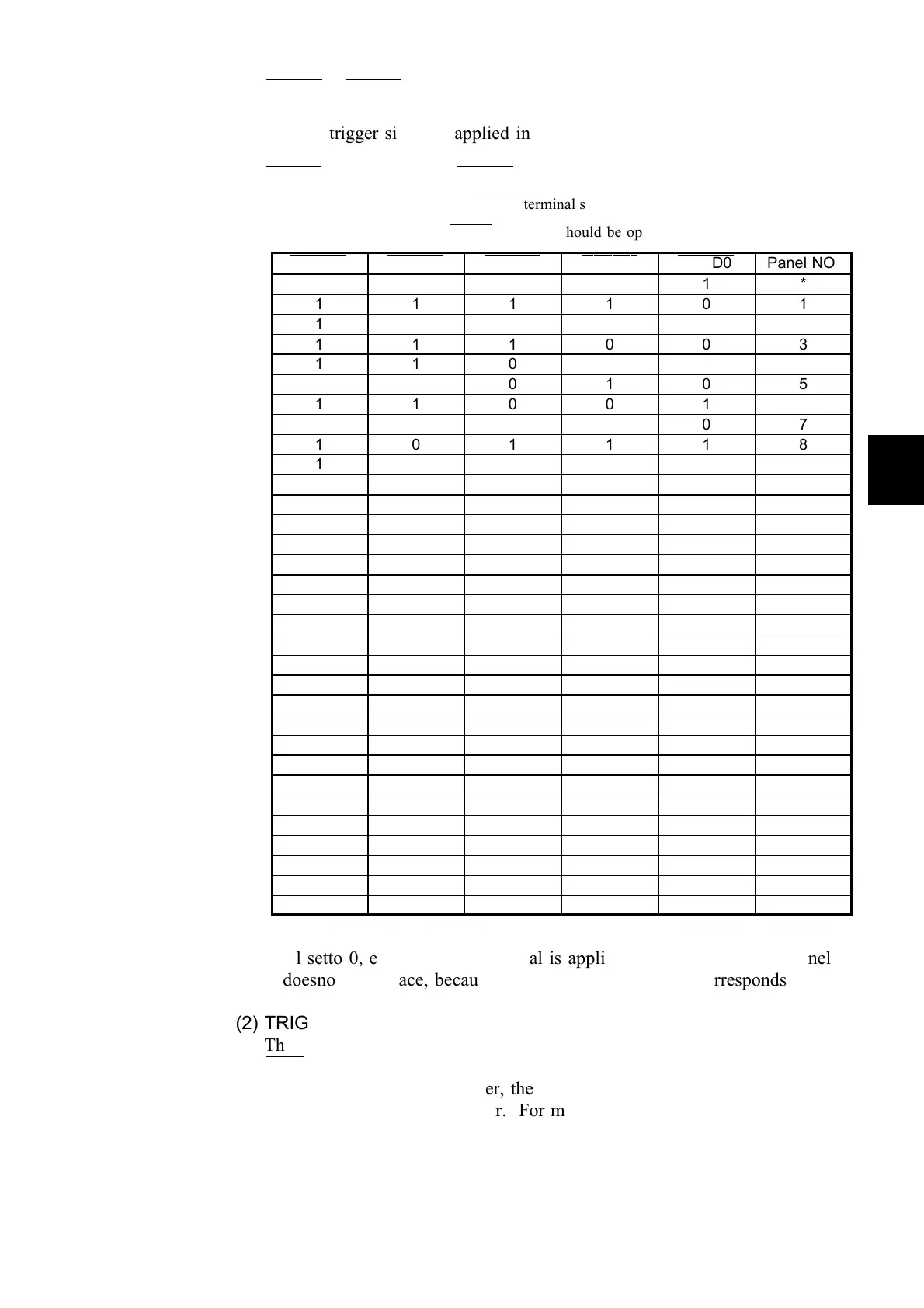
(The number 0 indicates that the LOAD
―――――――――
terminal should be shorted by the INT.GND, and the
number 1 indicates that the LOAD
―――――――――
terminal should be open.)
LOAD4
―――――――――
LOAD3
―――――――――
LOAD2
―――――――――
LOAD1
―――――――――
LOAD0
―――――――――
Panel NO.
1 1 1 1 1 *
1 1 1 1 0 1
1 1 1 0 1 2
1 1 1 0 0 3
1 1 0 1 1 4
1 1 0 1 0 5
1 1 0 0 1 6
1 1 0 0 0 7
1 0 1 1 1 8
1 0 1 1 0 9
1 0 1 0 1 10
1 0 1 0 0 11
1 0 0 1 1 12
1 0 0 1 0 13
1 0 0 0 1 14
1 0 0 0 0 15
0 1 1 1 1 16
0 1 1 1 0 17
0 1 1 0 1 18
0 1 1 0 0 19
0 1 0 1 1 20
0 1 0 1 0 21
0 1 0 0 1 22
0 1 0 0 0 23
0 0 1 1 1 24
0 0 1 1 0 25
0 0 1 0 1 26
0 0 1 0 0 27
0 0 0 1 1 28
0 0 0 1 0 29
0 0 0 0 1 30
0 0 0 0 0 *
(1) LOAD0
―――――――――
~LOAD4
―――――――――
These signals select the panel number from which to load data.
When a trigger signal is applied in External Trigger mode, the unit loads
data from the selected panel number and performs a measurement.
LOAD0
―――――――――
is the LSB, and LOAD4
―――――――――
is the MSB.
*: When LOAD0
―――――――――
to LOAD4
―――――――――
are all set to 1, or when LOAD0
―――――――――
to LOAD4
―――――――――
are
all setto 0, even if a trigger signal is applied, data loading from a panel
doesnot take place, because there is no panel number corresponds to them.
(2) TRIG
――――――
This signal places the unit in External Trigger mode. If you change
TRIG
――――――
signal from Hi to Lo, the unit will measure once at the edge.
If the interface is set to Printer, the unit performs a single measurement and
outputs the result to the printer. For more information on printers, refer to
Chapter 9. Printer Interface.
(3) INT.DCV, INT.GND
These signals output the internal 5 VDC of this unit and the internal GND.