57
_____________________________________________________________________________________________
7.2 Communication
______________________________________________________________________________________________
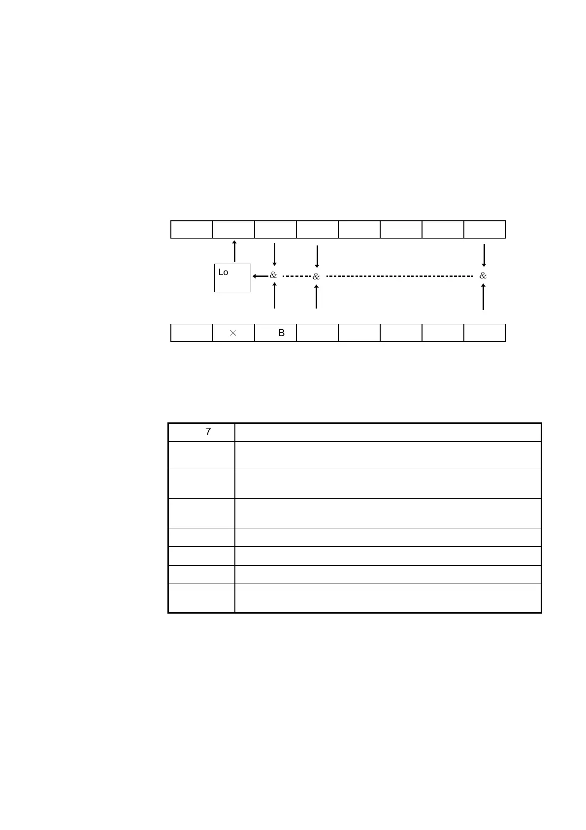
bit7 bit6 bit5 bit4 bit3 bit2 bit1 bit0
Not used
MSS ESB MAV
Not used Not used Not used
ESB0
&
&
Logical
sum
Status b
te re
isters
STB
bit7 bit6 bit5 bit4 bit3 bit2 bit1 bit0
Not used
×
ESB MAV
Not used Not used Not used
ESB0
Service re
uest enable re
isters
SRER
&
Bit 7
Not used
Bit 6
MSS
MSS shows the logical sum of other bits in the status byte register.
Bit 5
ESB
Standard event summary (logical sum) bit
ESB shows the logical sum of the standard event status register.
Bit 4
MAV
Message available
MAV indicates the output queue has messages.
Bit 3
Not used
Bit 2
Not used
Bit 1
Not used
Bit 0
ESB0
Event summary (logical sum) bit 0
ESB0 shows the logical sum of the event status register 0.
Status Byte Registers
(1) Status byte register (STB)
The status byte register is an 8-bit register whose contents are output from
the 3237/38/39 to the controller, when serial polling is being performed.
If even only one bit in the status byte register has changed from 0 to 1
(provided that it is a bit which has been set in the service request enable
register as a bit which can be used), then the MSS bit is set to 1.
Simultaneously with this the SRQ bit is set to 1, and service request is
generated.
Although the MSS bit is read out on an ∗STB?query,ona∗CLS command
for example it is not cleared until the event is cleared.
(2) Service request enable register (SRER)
This register masks the status byte register. Setting a bit of this register to 1
enables the corresponding bit of the status byte register to be used.
 Loading...


