A6
Measurement Probe Structure and Extension
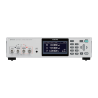
SOURCE-H SOURCE-LSENSE-LSENSE-H
Shield
SENSE side conductor
SOURCE side conductor
Zero adjustment jig
Prevent the SOURCE current from flowing into the SENSE side conductor.
If the current flows into the SENSE side conductor,
the voltage of the conductor resistance is
generated to cause an error.
Connect the conduction parts of the SOURCE
and the SENSE only with the one point.
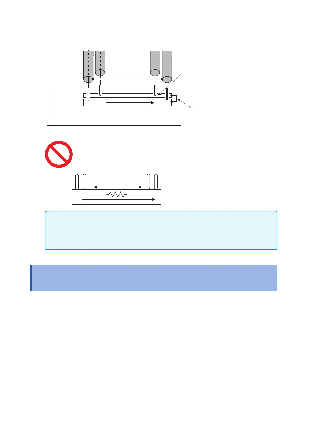
SOURCE-H SOURCE-L
SENSE-LSENSE-H
The voltage generates
When only one steel sheet (conductor) is used, an
error caused due to its conductor resistance.
IMPORTANT
• When making the measurement probe by yourself, you must be careful to not cause the short
circuit of any signal wire and the short circuit between the core wire and the shield wire.
• To prevent a short circuit, connect the probe terminal to the instrument and then connect the
battery.
Appx. 4 Measurement Probe Structure and
Extension
We can ll requests for probe extensions as a special order. Contact the distributor (store) from which you
purchased the instrument or your nearest Hioki sales ofce.
Observe the following precautions when extending the measurement probes by yourself.
• Use a thicker lead wire and a minimum length that you can prepare and implement as the extension.
• Extend the measurement probe with the four-terminal pair structure that is unchanged. In the case of the two-
terminal structure, the measurement value may be affected by the resistance of wiring and the contact, and
the inductive voltage. In the case of the four-terminal structure, the measurement value may be affected by the
inductive voltage.
• In parts other than the four-terminal pair structure, use an extension of as small a length as possible.
• Prepare shapes that are as similar as possible during the zero adjustment and the measurement.
• When extended, the measurement probe will have a greater voltage drop in the lead wire. The resistance of
the lead wire, including the resistance of the contact, must be kept within the allowable value.
• Keep the measurement probe away from metal parts. When the measurement probe is placed close to a metal
body, the measurement may not be correctly done due to the inuence of eddy currents.
• After extending the measurement probe, check the operation and the following:
1. By measuring the zero adjustment board, zero-point accuracy appears.
2. By measuring the master work (non-defective sample product) and comparing with the management value,
the measurement is done properly.