A7
Measurement Value in the Four-terminal Measurement (Difference in Measurement Value Due to the Measurement Probe)
Reduction method of inductive voltage
This instrument is subject to the inuence of the inductive voltage because of the measurement of a micro
resistance using AC. This inductive voltage means the voltage that is generated by the magnetic induction of
the measurement current owing in the lead wire which may affect the signal system of the measurement. The
inductive voltage has a phase difference of 90° from the AC current (reference signal), which can be removed
in the synchronous detection circuit theoretically. However, when the inductive voltage is excessive, the signal
is distorted, so that the inductive voltage cannot be removed in the synchronous detection circuit.
To reduce the inductive voltage, it is important that the measurement probe is as short as possible. It is very
effective to shorten the part where the four-terminal pair is not structured.
Appx. 5 Measurement Value in the Four-terminal
Measurement (Difference in Measurement
Value Due to the Measurement Probe)
For some measuring objects, different measurement values may be obtained depending on the measurement
probes used.
These differences between the measurement values are caused by the shapes of the tip and the dimensions
of the four-terminal probes used. Accordingly, each of the different measurement values is correct when the
corresponding probe is used.
You must use the same measurement probe when comparing the measurement values.
Explanation
The differences between the measurement values depend on the differences between the distances
(dimensions) of the pins to which the current is applied, and between the pins that voltage is detected of the
measurement probes.
The difference between the measurement values increases as the resistance of the battery terminals
increases in comparison to the battery internal resistance.
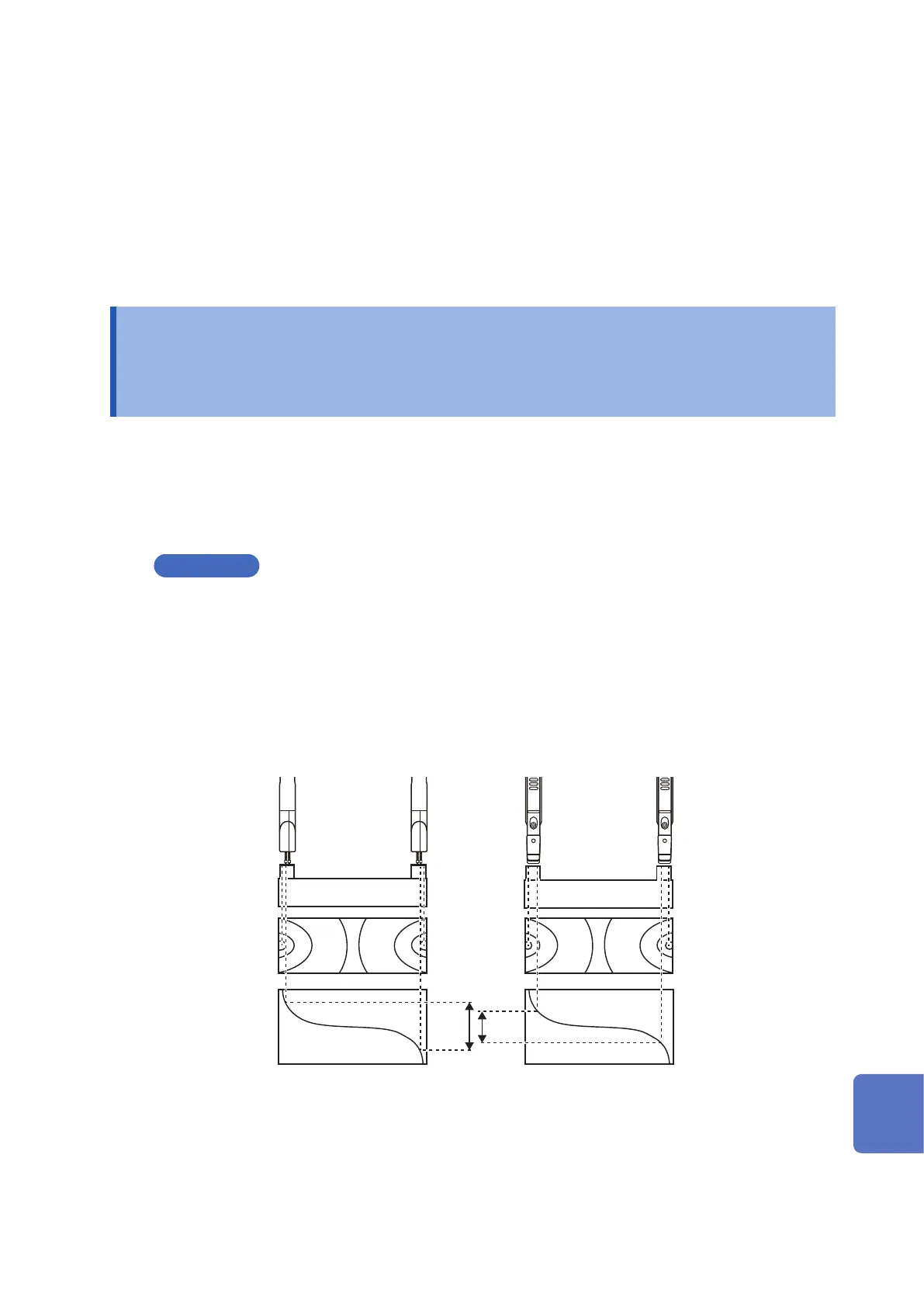
The gure below shows, as an example, the difference between the detection voltages that are caused by the
differences in the space of the probe pins when a large capacity battery was measured.
Pin Type Probe L2003
Pin spacing: 2.5 mm
Clip Type Probe L2002
Spacing: 6.3 mm
+
terminal
+
terminal
-
terminal
-
terminal
Battery
Battery
Equipotential line
Potential slope Potential slope
Equipotential line
A
B
V (detected voltage): A>B
10
9
8
7
6
5
4
3
2
1
Appx. Ind.