A13
Precautions When Making the Switching Unit
Appx. 9 Precautions When Making the Switching
Unit
When placing the switching unit between the
instrument and the measuring object, you must
make the switching unit with the four-terminal pair
connection. Here, when making the switching unit,
precautions including performing the four-terminal
pair connection are described.
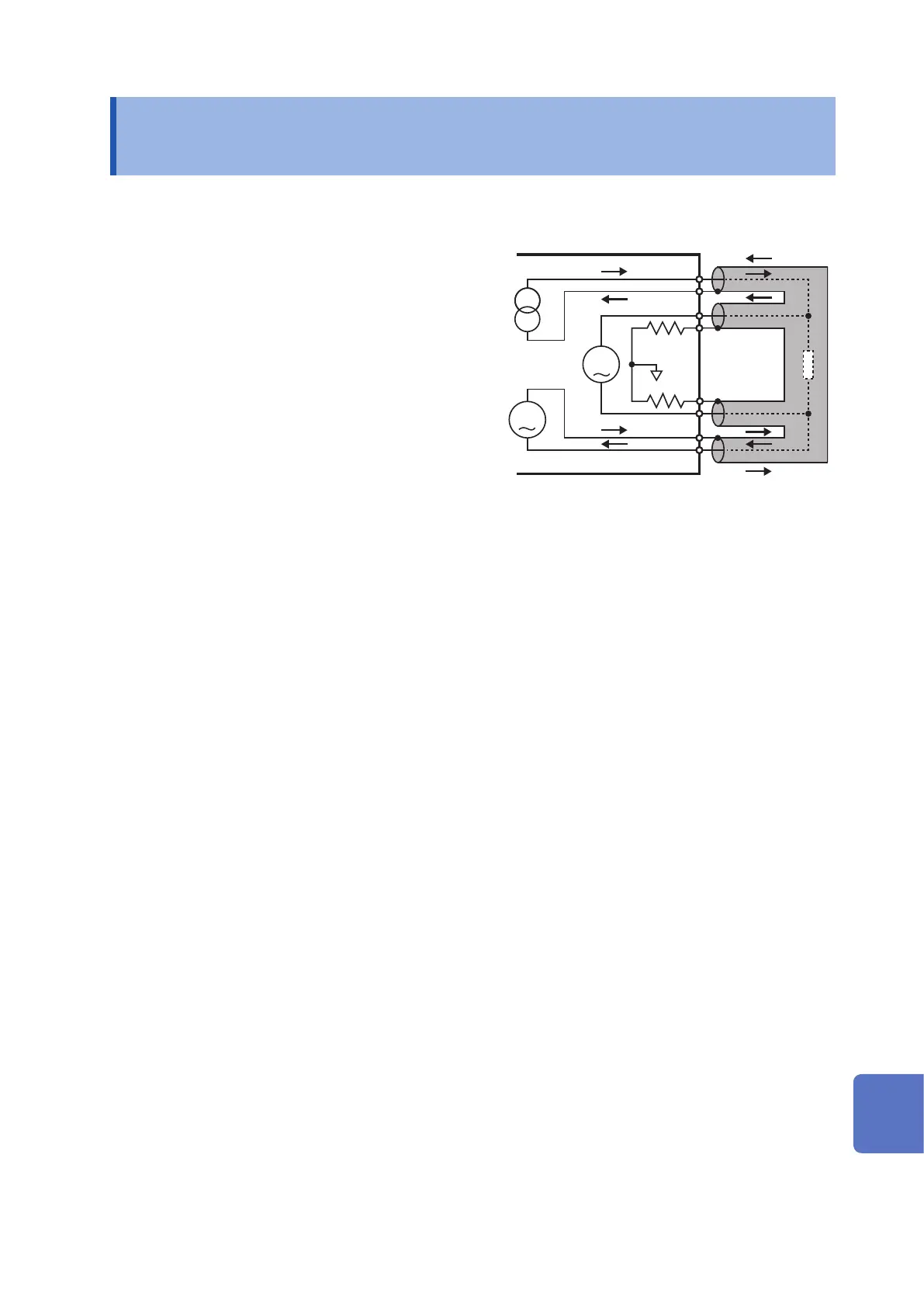
This instrument has the measurement terminals
with the four-terminal pair connection structure.
(Figure. Four-Terminal Pair Connection Structure)
This four-terminal pair connection structure prevents
the magnetic eld created by the measurement
current from generating and suppresses an inductive
electromotive force to the voltage measurement
terminals. The inductive electromagnetic force
becomes noise to the measurement voltage,
which must be suppressed as much as possible.
The inductive electromagnetic force also must be
suppressed in the switching unit.
V
A
SOURCE-H
SENSE-H
SENSE-L
SOURCE-L
Figure. Four-terminal pair connection structure
Observe the following methods to suppress the inductive electromotive force.
• The loop area formed by the ow-out wire (core wire) and the ow-in wire (shield wire) of the SOURCE-H
terminal must be as small as possible.
• The loop area formed by the ow-in wire (core wire) and the ow-out wire (shield wire) of the SOURCE-L
terminal must be as small as possible.
• The loop area made by the detection wire (core wire) of the SENSE-H terminal and the detection wire (core
wire) of the SENSE-L terminal must be as small as possible.
• The loop formed by the SOURCE wires and the loop formed by the SENSE wires must be kept away from
each other.
• The loop formed by the SOURCE wires and the loop formed by the SENSE wires must not be face each other
The relays that are used in the switching unit must observe the following.
• For the relays, 2a or 2c contact type must be used, and the area of each loop must be as small as possible.
• The relays with the rated current that exceeds the measurement current of this instrument (the maximum
current is 2.12 A at the measurement current 1.5 Arms) must be used to change over the SOURCE terminals.
• For changing over the SENSE terminals, the latching relays must be used to suppress the effect of the
inductive electromagnetic force.
• Furthermore, for changing over the SENSE terminals, the relays with the Au clad cross-bar twin contact type
or AgPd contact type must be used to ensure the reliability of the relay contacts.
Integrating the above points, the Pattern layout examples (in the case of the single-sided board) of the
switching unit gure is shown. When designing the patterns with two or more layers, the loop can be minimized
by layering a pair of patterns over it. (Figure. Pattern Layout Examples of the Switching Unit (in the case of the
substrate with the two or more layers))
10
9
8
7
6
5
4
3
2
1
Appx. Ind.