84
Timing Chart
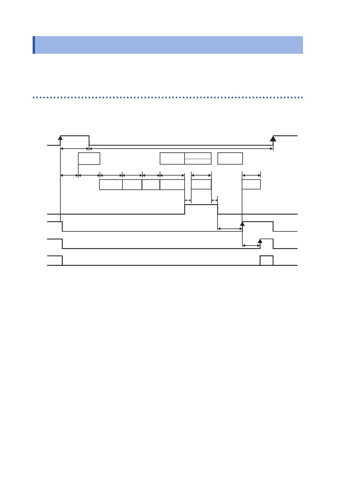
8.2 Timing Chart
The levels of each signal indicate the ON/OFF status of the contacts. In the case of the current
source (PNP) setting, the signal levels are the same as the voltage level of the EXT.I/O terminals.
In the case of the current sink (NPN) setting, the High and Low voltage levels are reversed.
Acquiring the judgment results after starting measurement
(1) When the external trigger [EXT] is set
In the case of measurement functions (R, X, V, T), (Z,
θ
, V, T)
TRIG
ON
ON
Measurement
current abnor-
mality (moni-
tored between
t-2 and t-3, and
between t10
and t8 and t11.)
Measurement
processing
Measurement
current
INDEX
EOM
Judgment
result
Contact er-
ror detection
Over-voltage input
error detection
Measurement current
fault detection
Voltage drift detection
Contact error
detection
Self-
Calibration
V sam-
pling
V calcu-
lation
Z sampling
Z calculation
t2 t3 t4 t5 t6 t7
t10
t8 t9
t3
t9
Stop
OFF
OFF
OFF
ON
ON
OFF
OFF
stop
Application
Switching mea-
surement circuit
t11
t0 t1
Judgment results: HI, IN, LO, PASS, FAIL, ERR