85
Timing Chart
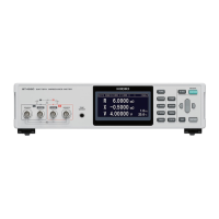
In the case of measurement functions (R, X, T), (Z,
θ
, T)
TRIG
ON
Measurement
current abnormal-
ity (monitored
between t-2 and
t-3, and between
t10 and t8 and t11.)
Measurement
processing
Measurement
current
INDEX
EOM
Judgment
result
Contact error
detection
Measurement current
fault detection
Voltage drift detection
Z sampling
Z calculation
t2 t3 t7
t10
t8 t9
Stop
OFF
OFF
OFF
ON
ON
OFF
OFF
Over-voltage input
error detection
Contact error
detection
ON
OFF
t3
t9
StopApplication
t11
Switching mea-
surement circuit
t0 t1
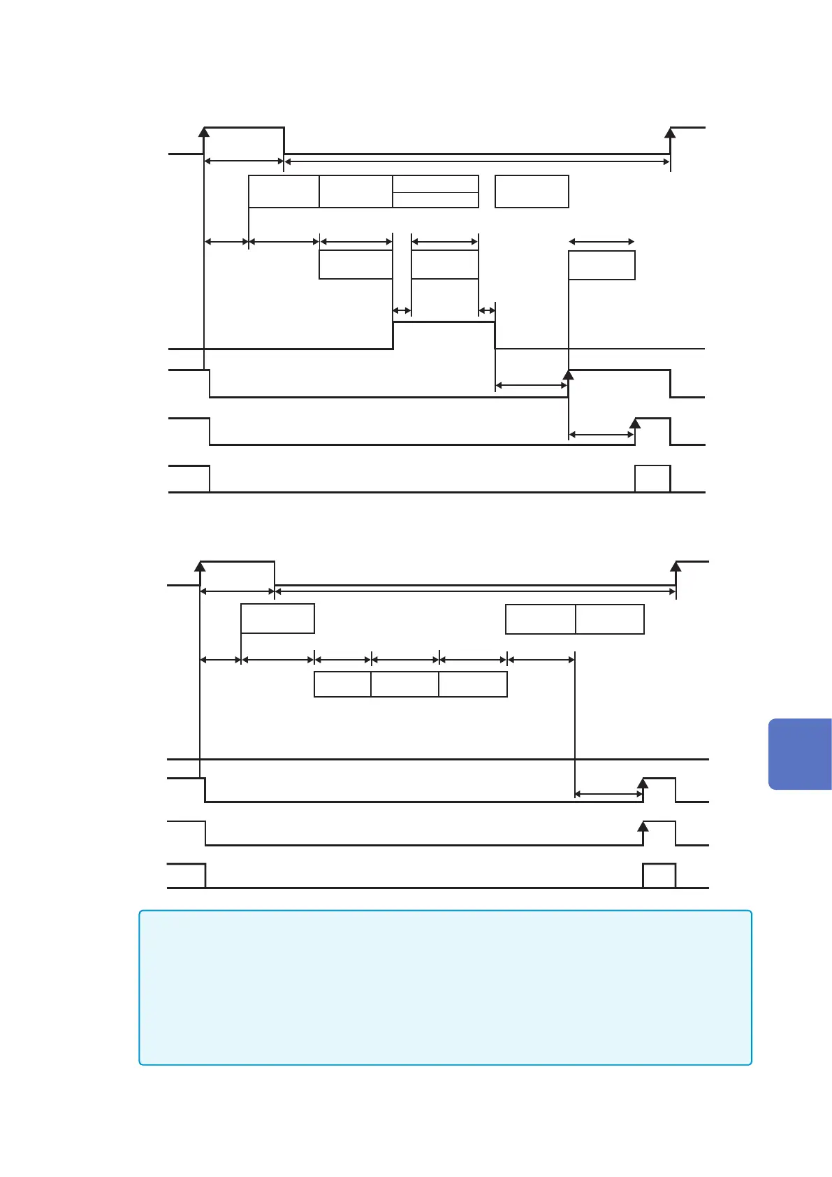
In the case of measurement functions (V, T)
TRIG
ON
Measurement
current
abnormality
(monitored
between t-2
and t-3)
Measurement
processing
Measurement
current
INDEX
EOM
Judgment
result
Contact error
detection
V sampling
V calculation
t2 t3 t7
stop
OFF
OFF
OFF
Over-voltage input
error detection
Contact error
detection
ON
Self-
Calibration
t4 t5 t6
t3
ON
ON
OFF
OFF
OFF
t0 t1
• Do not input TRIG signal when measurement (INDEX signal is OFF) is in progress.
• When settings such as measurement frequency are changed, input the TRIG signal after the
processing time (approx. 15 ms).
• The input signal is disabled when the measurement screen is not open, or when an error
message is displayed.
• The output of the judgment result is determined before the EOM signal becomes ON. When
the response of the controller input circuit is slow, a wait is required from when the EOM signal
ON is detected until the judgment results are read.
8
External Control (EXT.I/O)